 |
|
| This, the second of Terry's articles on this site, shows in greater detail just how much work is required to make a flying boat out of nothing other than a block of wood. I'm sure you will agree that his workmanship is exquisite ~ and remember this is wood ~ and 1/144th scale!!! |
|
I have always been attracted to seaplanes and especially the big biplane boats from between the wars. I just love the graceful lines of the seaplanes planning hull, it amazes me that these flimsy looking giants could withstand the rigors of landing and taking off from water. I already had a Short Singapore in my collection, and I had recently added a Short Kent, I needed the Short Calcutta to complete an obvious trio. The following photos describe the building of the Calcutta.
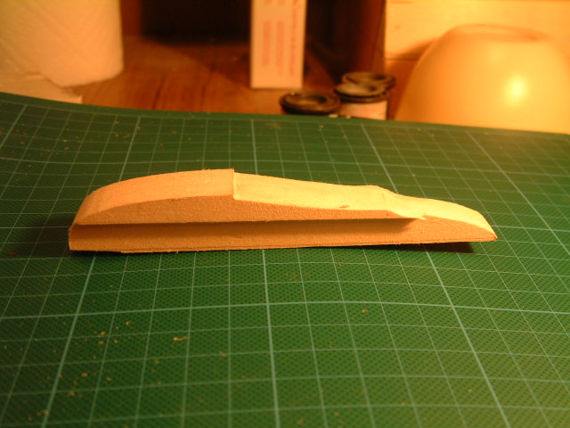
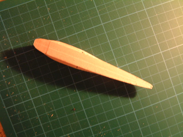
In Photos 1
&
2 the
basic fuselage, roughed out in side and top profile, the extra width
for the planning bottom is clearly visible.
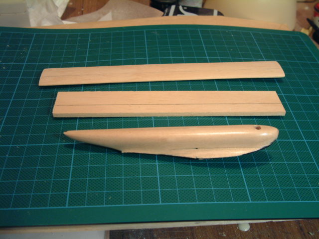
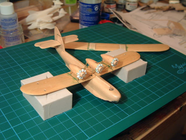
In Photo 3, the fuselage is fully carved, sanded and grain filled, in fact the sanding - filling sequence would have taken place three or four times. Directly behind the fuselage is the lower wing, the line drawn from end to end is at 1/3rd chord, this is a carving aid. Most, and I believe all early wings, had maximum thickness or depth at approx 1/3rd cord, this line greatly assists the carving of the aerofoil section, the line should be at least faintly visible when the wing is fully carved and sanded. At
the rear of the picture is the upper wing, it has been carved into an
aerofoil section, but the wings plan form has yet to be carved and
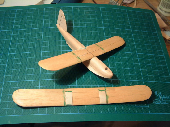
shaped. Photo
4 shows the wings
have been fully finished, dihedral has been added as has the over-wing
fuel tanks. Also at this
stage the model would have received two or three more sanding -
filling operations, this is to ensure that joints are blended and
all the surfaces have a consistent surface finish or texture.
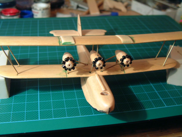
The engine nacelles were carved and the short lengths of plastic tube cut and glued into position to form the radial engines. Next the tailplane was added, when fixing butt jointed components, I always cut an extremely thin sliver of wood, and insert it into a slot cut into the end of the component. I then cut a slot in the fuselage or what ever the component is to be fixed to, this allows a trial joint to be made. The position can then be adjusted by moving the position of the slot slightly. When you are sure everything is correct the joint can be glued, the embedded splinter of wood adding to the strength of the glued joint. I
fixed the tail plane into position at this stage because I considered
that it would help with the aligning of the engines/engine struts.
The struts were then attached to the bottom of the engines, the
exact length of the struts was then adjusted until the engines sat in
the correct position. Because
I am working in wood I always indent the wood at the point where the
struts attach, this allows for a stronger joint. The indents for the mainplane struts can be seen in this
picture. All of this can be seen
in
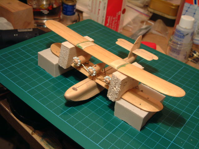
Photo 5. Photo
6 shows the soft balsa blocks that were cut and shaped so that they
held the upper wing at the correct spacing from the lower wing.
Photo
7 shows the pieces of balsa that were added to ensure the wing was
held in position with the correct amount of stagger. All
of this careful positioning will come to nothing if everything is not
also held firmly in position, so elastic bands are used to achieve
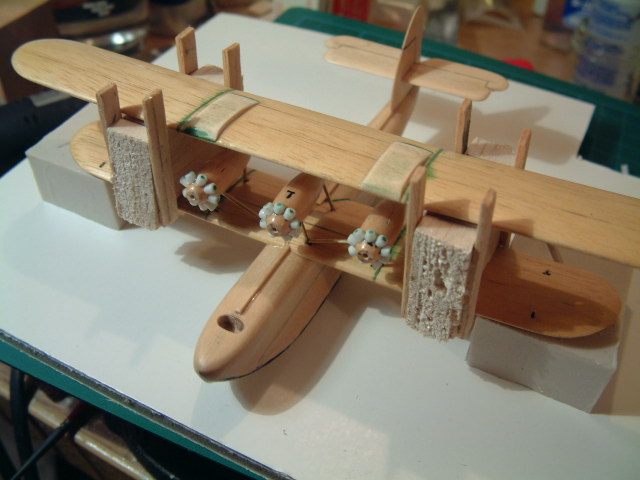
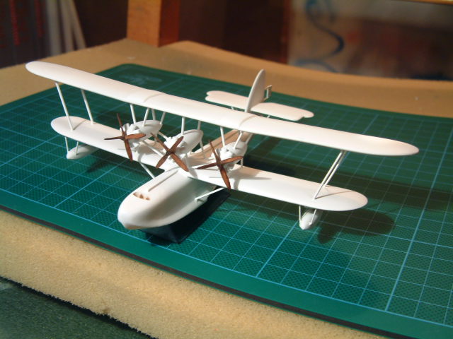
this. It can be seen in Photo 8 that the two central struts and the four outboard wing struts
have now been fixed into position. In Photo
9,
it can be seen that the holding blocks have been removed and the six
main struts give the model sufficient strength for the rest of the
work of strut fixing to continue.
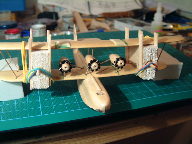
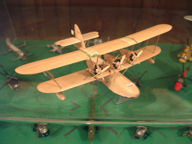
Photo 10 shows that the floats and propellers have been carved, the engine to wing struts, tail plane struts and float struts have all been cut to size and fitted. The pilots seats have been added but as yet no windscreen, that cannot be added until after final painting. At
last a coat of paint in Photo
11, unfortunately this is often the
point at which surface faults and poorly made joints become apparent,
but Im pleased to say that this one doesnt look too bad.
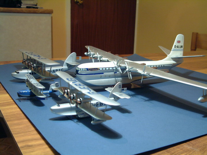
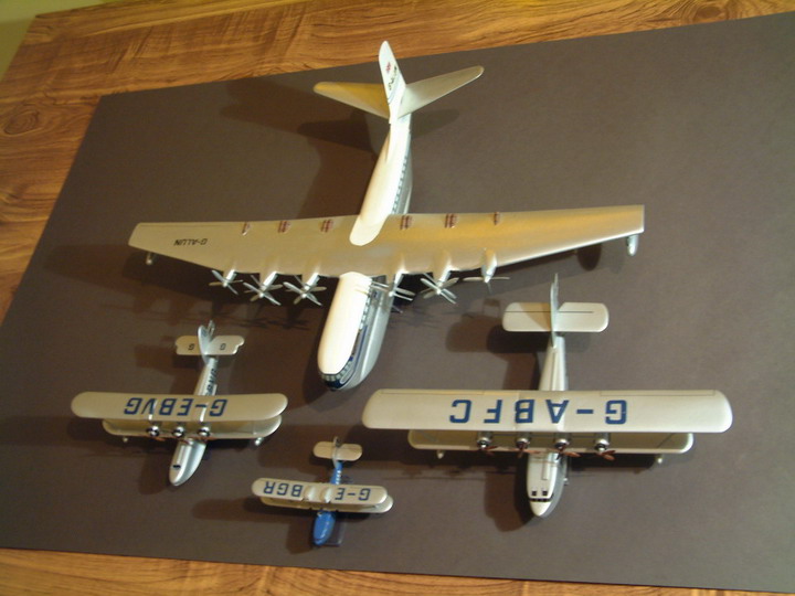
In Photos 12 & 13, she is posed with some of my other flying boats, namely, the Supermarine Sea Eagle, Short Kent and the magnificent Saunders Roe Princess. Both the Calcutta and the Sea Eagle still await their Imperial Airways decals. |