 |
|
| (Reproduced from Scale Models International Vol 19 Number 230 - December 1988 Author: Bryan Ribbans) |
 |
 |
 |
 |
 |
|
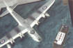
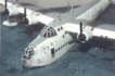
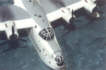
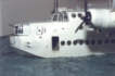
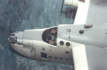
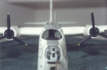
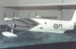
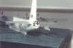
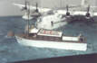
Flying boats, especially the larger types, have always held a special fascination for me. I can remember the last Sunderland to be based at Felixstowe flying over my house in a fare-well low level fly-past and the sight and sounds were incredible. The noise from the four Pratt and Whitney Twin Wasps at full take off power could be heard for miles around. So, a chance conversation many years later with a contact of mine, began a series of events culminating in a model diorama depicting a Short Sunderland Mk.V at her mooring point when based at Seletar, Singapore during 1951. He had served his National Service as a crew member aboard M-Mike, RN288, with 205 Squadron Royal Air Force, and wanted a model made of her. My first major task was to find as much good reference material as possible and my contact provided me with a number of clear photos of M-Mike and other aircraft of the squadron that he had taken during his stay. Secondly, I scoured all the books and magazines I could find in my collection, and also the library, for the little details that would make the model just that bit more authentic. Knowing that a full-sized Mk.V was being restored at Duxford a telephone call brought forth a kind invitation to examine, at very close quarters, their example. So, armed with camera and sketch pad, I arrived one Sunday and spent a few hours climbing over various parts spread around the main hulk (as it was then) familiarising myself with the details. The restoration team there were very helpful in answering my questions and also allowing me to go inside the hull. This helped a great deal in sorting out what goes where in the cut-away drawings I had to hand at the time. A BREAKTHROUGH Then, as these things tend to happen from time to time, I learnt that Norman Harry, who had worked with Shorts at Rochester, lived in the next street to me! Well, that was too good an opportunity to miss so I gave him a call to see if he could help. He turned up at my workshop, one evening, armed with virtually everything one could ask for on the type, including the handbook! Following a long discussion and the swapping of a spare Sunderland kit, I was the proud possessor of copy photos and drawings of every crew position and internal detail you can think of. Having completed my research, I looked about to see which kit I could use. As any longstanding modeler knows, the only kit in 1:72 scale is the old Airfix Mk.III (which is almost as old as I am!) and shows its pedigree with all the working gimmicks which were then the 'in thing'. I did consider, especially with all the research material I had gathered, building Combat Model's huge 1:48 scale vacform, but in the end decided against this as I would prefer to build something else in the next 10 years! So the Airfix kit had to do. Overall, the kit's accuracy isn't too bad. I'm not a rivet-counter, therefore providing the outline was close, then I reckoned I could handle the rest. The parts breakdown is elementary compared to today's kits, t e main items being the two hull halves, four wing halves (upper and lower) and the same for the empennage. The Pegasus engines, with which the earlier marks were fitted, came as impressions within the nacelle mouldings but are grossly undersized as the cowling lip is far too thick at this point which, I suspect, is due to moulding limitations. Actually, throughout the kit all the parts are very heavily moulded which turned out to be a blessing in disguise as you will see later. DIFFERENCES The first thing to do was to list all the differences between the kit Mk. III and the later Mk.V. Broadly speaking these involve the change in nacelle shape to accommodate the Twin Wasp engines, different front and rear gun turrets, deletion of the mid-upper turret, altering the number of portholes on both sides of the hull and adding the centrimetric radar scanner housings under each wing. Also, the kit parts required a number of details to be redefined, or altered completely, such as the air intakes between the engine nacelles as these are nothing more than large holes in the original kit. When considering the interior, apart from a rudimentary cockpit floor and 'blob' type seats, there is nothing else, therefore I had to consider what style of presentation the finished model should take. Really, there was no decision to make as with the wealth of internal references to hand it would have been criminal not to put them to good use. Also at this juncture, I had in mind to make a diorama as I also had some good references for one of the RAF's launches as used at Seletar. Therefore, I elected to show the port crew entrance door fully open to reveal the lower deck bow compartment and door leading to the wardroom and galley. The cockpit canopy was to be removable to enable a view aft to be seen along the upper deck from the cockpit, past the various crew positions, to the main rear hatch which separates the crew from the bomb bay. Now it was time to cut plastic. CONSTRUCTION COMMENCES First, the two hull halves were cleaned up and the correct water line established. This was marked with an Olfa P-Cutter and gently scored until the lower hull could be snapped away. Then the starboard and port crew doors were scored in, the port one being removed altogether, and the rear gunners door under the starboard tailplane was also scored in. The scoring was done by making a template from 30 thou. plastic card to the outside dimensions of the doors and then placing this onto the hull in the correct position and running a pin held in a pin vice around the inside of the template aperture a few times. If the door access panel happens to be on a curved surface just use thinner plastic for the template and fix it to the fuselage with masking tape. Bomb bay hull doors for the Mk.V differed from earlier marks in that they had only two portholes, not three. Using the kit item as a pattern over 40 thou. two new ones were produced with the required portholes being marked out and drilled using progressively larger drill bits until they matched the kit ones. These were then glued to the hull. Other portholes had to be deleted and as these were situated outside of the area I was going to detail then all I did was to back them off with card and fill with Milliput. They could then be sanded with wet and dry paper to blend in with the hull lines. Various escape hatches and gunners hatches were also scored in at this time as it helps to have the hull on its side with a block of wood underneath whilst doing this for support. The port door had the plastic around it filed down to scale thickness and the forward turret area also had the opening widened from the kit size and thinned down. Using various plans and illustrations, I then set about the task of marking out the deck levels and the vertical bulkheads. I took my time over this as one wrong move would result in a bulkhead crossing a porthole or the deck levels being uneven. I drew myself an overlay in tracing paper of the Aviation News plans and marked out on this the relevant areas which concerned me. From this I then cut the decks from 30 thou. and then the bulkheads from 20 or 30 thou. depending where they were due to go. Each deck was then offered to the hull halves and trimmed to allow for any small deviations. When this had been done for both hull halves, the bottom deck was cemented firmly in place into the port hull half. Small tabs of triangular section were glued under the deck against the hull for added strength as the last thing I needed on the deck was a twist. Each bulkhead was then glued in turn to this deck working from front to rear thereby placing the wardroom, galley and other areas. Each was again reinforced with hidden tabs and left to harden off overnight. When dry, the upper deck was glued into position and bulkheads aligned with each hull half. Each time I placed a bulkhead the starboard hull half was offered up and the plastic card trimmed to fit. It was not really any different to sorting out the fuselage of a large vacform. I had then, the port hull half containing all the crew stations in its barest form and it made the cut down hull very strong and rigid. MONTHS OF WORK Now the real work began. I glued strips of card over the wing root areas and detailed this with stringers of Microstrip. Next, the whole of both hull halves were detailed using the same material being careful on the starboard half not to cross any bulkhead positions. Having seen the interior of the full-size machine it would be virtually impossible in this scale to include every stringer as there are hundreds exposed the whole length of the hull, therefore I aimed at getting a good representation of this. When complete, I turned my attention to each bulkhead with the Microstrip and oddments of scrap and detailed the forward faces of each one. Some of the doors were proud of the bulkhead faces on the real thing so this made life a little easier. I marked on the floor or bulkhead of each crew station the position of seats, equipment, tables and various other items then painted in the corners of each station which, when finished, would not allow me to reach with a paintbrush . Then I spent the next few months (Yes, I did say months!) building all the interior equipment using the handbook drawings and photos culled from my sources. I was conscious of the fact that the only way to view all of this was from the front of the cockpit and I took this into account when detailing. Where a particular item of equipment was tucked away at the rear of the crew cabin I used scraps of decal to add an impression of dials or switches etc, whereas further forward, more precise detail was shown. The overall impression when looking at the finished deck is not lost by doing this, in fact, they look very realistic at the rear end. By taking each crew position one at a time and treating it to the paint-as-you-go principle, it slowly began to come together and the jigsaw fell into place. During this time I had also worked on the starboard hull half and following a number of trial fittings, cemented them together. Because of the water-line configuration I was able to create a really strong bond between the decks and the hull and, when dry, the whole fuselage was very strong. Some may say that they wouldn't have bothered with going this far but sitting back and looking at the hull I found that I could see 90% of what I had put in and, as for the other 10%, well it is nice to know that it's there. The trickiest bit was now to mark out and place the four upper hull escape hatches and portholes and drill these through without hitting anything inside for, if that were to happen, then I might as well pack up because, with the inside finished, it would then be irrepairable. After much consultation with the afore- mentioned tracing, there was nothing left but to do it. The worst one was the forward astrodome as there exists a control panel directly beside this and so a small drill was used and a torch shone through the hole to see where I had come out. As it happened, I need not have worried, it was bang on! I enlarged it to the proper size using, again, progressively larger drill bits and did the same for the other three. THE ENGINES As I mentioned at the start, one of the major changes to the Mk.V was the addition of Pratt and Whitneys for increased power. Also the exhausts and cowlings were altered, therefore the kit parts were discarded. A spare set of Airfix Stirling cowlings fitted the bill nicely. These were shaped more precisely and the P-Cutter run around their circumference to produce the panel lines. Five thou. plastic card was used to form the gills by firstly cutting a strip which matched the circumference and then slitting it in the right place for each gill position. Aeroclub white metal engines were slightly cut down to fit the interior of each cowling, then epoxied into place. The prominent air intake within the upper cowling interior was bent up from 10 thou. and judiciously cut until they fitted and looked right. Any gaps were filled with Green Stuff or liquid cement. The exhausts were a head ache. I considered all ways of producing them including casting, but in the end settled for the old way. That is, over a period of weeks I cut, shaped, formed and cursed my way through each one individually by taking an over length piece of sprue the diameter of the pipe, bending it to the required shape, cutting a slit horizontally in the end and inserting a triangular piece of 10 thou. card which approximated the plan view of the ejector. Then using Milliput, I built up the profile until I had the required shape. This was then sanded to match the previous one. In the end I think I made about a dozen of which I picked the best eight and put them into matched pairs. Aeroclub white metal Hamilton Standard props of the correct size finished this area off quite nicely. The wing halves were glued together with tube glue and left to dry. Then, off came the nacelle protrusions and the holes for the air intakes were cut away. Also at this time I cut out the areas for the navigation lights which were made in the time-honoured fashion of a piece of clear sprue with a drilled hole in the rear into which a drop of red or green paint was placed. These were then glued into the wing cut-outs and sanded down with the rest of the wing when the time came. The air intakes were formed by placing two pieces of Plastruct square section tube into the front of the wing and closing off the see-through look with scrap card. Then the aerofoil shape of the wings was restored with Milliput which was smoothed over with a wet finger after application and sanded when dry. At this point I now had a decision to make. My references and plans showed that one of the kit's failings is that to make the ailerons operable they are actually larger than they should be and they extend into the wing chord too far. However, the difference isn't really that great so I decided to leave well alone and to settle for detailed actuating rods and cables in an effort to hide this. When you look at photographs of the real thing and then the kit, unless you have the plans to hand, it is difficult to spot and the average onlooker would probably not notice at all. The wings were then scribed with panel detail and an impression of the fuel tank locations was added using 5 thou. card. All the overdone panel lines from the kit were sanded off. (Including the rivets on the hull). Other small inspection panels in various places were added using 5 thou. The cowlings were affixed to the nacelles and adjusted until they each sat right. A plan view of the radar housings was cut from 20 thou. card, slightly smaller than required, and to this was added a vertical profile cut out of the same card, also slightly smaller. This cruci-form arrangement was filled in with scrap sprue and topped off with Milliput which, when dry and sanded, gave me a male mould to produce the housing. A female mould was cut out of balsa and a number of mouldings were made from which the best two were used. These were then trimmed to fit the wing and cemented in place. The floats were now dealt with and because I had been able to see the real thing at first-hand I could detail these quite accurately by adding small pieces of 5 thou. to represent the access hatches etc. New struts were made using Contrail rod and these were attached to the floats and the complete units attached to the wings. That just left the wings to be affixed to the hull. By virtue of the fact that the kit is an old one the wings are a butt joint on to a small section of the wing moulded with the hull, but this caused me no problems. In fact, it probably saved me a nasty clean up job on the lower wing root. The hull was put in a temporary card jig fixed to the work bench then each wing was attached using epoxy, then super glue, followed by copious a mounts of liquid cement. This was one wing that wasn't going to come adrift! It stayed in the jig for a couple of days to really set and, whilst I was waiting, the empennage received similar treatment. At last I had the major work completed so next I started on the launch. ALL AT SEA! Having got the photos I set about scaling a plan using what I could see in them. Knowing the size of standard items such as lifebelts, oil drums and the like, plus crewmen standing on it, I am sure that the plan I finished up with is pretty close to being correct. Using various parts from an Airfix RAF Whaleback kit and the Vosper MTB I gathered together all the usable bits and matched them to the plan and photos. In the event, most of the launch was scratchbuilt. I started with a piece of 40 thou. card for the base of the hull as it's a waterline model only and to this attached the rear three-quarters of the Whaleback hull. The bow section was formed from profiles cut out of card, then these were joined by stringers and all were smoothed over with Milliput, before sanding with wet and dry paper to give a continuous line from front to rear. A strip of card formed the chine line. A false floor was fitted at the rear using Tamiya square section rod onto which was mounted plastic card scribed with floor detail and then the cabin sides were cut out together so that the windows would line up. The deck was added now as a complete cover over the hull and, when dry, the cabin area was cut away in the correct places. This saved having any unsightly join lines down the deck. The cabin front was cut out and the areas to be glazed cut from this. All the superstructure was now fitted using liquid cement and when dry the cabin interior was detailed starting from the rear and working forward, much the same as the Sunderland. This included making items such as flasks and mugs for the crew and fitting out the forward part with instrument panels and radio, all from scrap card and oddments. When I was satisfied I fitted the roof. Final detailing now took place utilising items from the Airfix kits such as the air intakes, searchlight and lifebelts, with others coming from the spares box. Having painted the interior as I went along all that remained was the exterior so the launch was set aside for this. LET US PAINT! With most of the major work on the Sunderland done, it was now time to paint the exterior. So, after a thorough clean up and masking, a coat of Humbrol } Matt White was applied over the hull and wings using a Badger 200 airbrush. This revealed the usual crop of minor defects which were dealt with by filling, sanding out and re-spraying. A change was then made to Compucolor Satin White and six white coats were sprayed on over a week, sanding lightly in between, to obtain a pure white finish. The airframe was further masked and Humbrol Medium Sea Grey, heavily lightened with Matt White applied to the upper wings and hull. Because of the intense sunlight under which these aircraft operated, the grey became a pale shadow of its true colour, hence the white. I experimented with several shades of this before I settled on the final outcome as I had to balance this tone with the overall effect of the diorama colours and I found that if I went any lighter than this it began to look a little odd. Personal preferences prevail! Once dry, the masking was removed to reveal the beast in all her glory! The liquid masking which had covered the portholes, and the tissue stuffed in the doors and covered with the same, was now removed being replaced by Microscale Kristal Kleer applied with a tooth-pick into the portholes. A couple of coats of clear varnish were then applied overall. The wing roundels came from the Matchbox 1:32 scale Sea Venom, they are just the right size as are the tail flashes. The hull roundels came from the spares box together with small stencils and the like. The large M was cut from solid black decal and the serial is from Letraset. The Squadron badge over the port door was adapted from a Matchbox Halifax decal, the centre being cut out and the 205 symbol being hand-painted. The Ace of Clubs badge was made up from various odds and ends all superimposed onto white decal. When all was in place a final coat of satin varnish was applied to the hull followed by a matt coat over the upper surfaces. Then all the tiny aerials and their fittings were added. THE GUN TURRETS The final items to be added were, perhaps, the trickiest of all. Having gone to so much trouble to include as much detail as possible I was left with the two gun turrets, front and rear. Firstly, I threw away the kit items and for the rear turret I found an old Airfix Stirling one which was thick enough to hack about. The parts were glued together and filled with Milliput. Layers of 20 thou. card were built up on the bottom edge to give me the required height. To the base was attached a strong length of sprue runner to form a handle for moulding. I then sanded with wet and dry paper, used wet, until I had the correct overall shape .With a sharp scalpel, I cut a groove into the turret which corresponded with the join between the glazing and the metal rear of the real thing and then, following a clean up and polish, moulded (using the male/female process) a number of samples in both white and clear card. Selecting the best one of each type, I placed these back over the male form and following the groove with the scalpel, cut apart each one down this line. On the mould again, I marked out the gun apertures and placed the clear part back onto this for further cutting out. I constructed a floor for the turret out of 20 thou. card and following references built the interior out of scraps of card and oddments from the spares box. Because of the scale, and the fact that the real thing is packed with equipment, it was an extremely difficult job. Both turrets took the best part of a month to get right and I don't recommend this exercise to anyone. Still, the effect when placed on the hull was stunning! The interior having been painted, I used black decal, then white, to represent the glazing bars taking care to let the black decal fully dry out before overlaying the white on it. (Thinks, if you are looking from the inside out, what do you see?) Guns were found in the scrap box, cut to size and painted gunmetal before rubbing with pencil lead and fixing to the turret with super glue. The front turret followed exactly the same format, even using an old Stirling one as a start and this, when finished, was placed into the modified Sunderland kit housing. This, having been painted along with the main airframe, was glued onto the hull set slightly back to show the detail in the bow compartment. The cockpit canopy supplied with the kit is a very poor moulding being over-thick, not quite the right shape and very scratched by the years of mould use. I mentioned earlier that I was going to leave this item removable so set about making a new one. I filled the kit canopy with Milliput and before this had fully set, pushed into it another length of thick sprue runner. This I now left to harden. A few hours later began the task of sanding the kit part to the correct outline with wet and dry, used wet. When I was satisfied with the overall shape compared to both the plans and to the 'gap' to be filled in the hull then a number of moulds were taken in both 20 thou. white and clear card. Placing one of the opaque forms back over the male mould I marked out with thin strips of masking tape all the glazing, firstly by placing the fore and aft window edges, then the horizontal ones. These were then drawn around with a hard, sharp pencil and the masking tape removed to leave all the window outlines in place. A pin vice with a very fine drill was used to run around the inside of the lines and a scalpel followed this to join them all up. Out popped the areas to be glazed. After cleaning up the window aperture with a swiss file, the clear moulding was placed over the male mould and its edges tidied up. This was then cemented very carefully INSIDE the window frame and it fitted a treat. When dry, the cockpit windows were filled, up to the outer frame level, with repeated applications of Kristal Kleer. It is far better to apply thin layers over again then run the risk of having the window go cloudy through using too much. FINAL DETAILS The small windshields on each side of the canopy were made of scraps of clear card, the windscreen wipers added from sprue, and the canopy frames hand-painted using the upper surface paint mix. Lastly, the fine details were added. Tiny hull handholds were drilled and thin slivers of stretched sprue were then fitted into these for the holding bar itself. Then the hull and wings were weathered using pastels and thinned oil paint until I was satisfied with the effect. The whole aircraft was fixed to a previously made base by gluing onto 40. thou plastic card with epoxy, the card having been fixed to the base by the same material. The launch was also epoxied to the base along with the buoy. The 'sea' effect was obtained by applying Polyfilla on the base and shaping it when still wet to form swells. Then this was covered with a layer of PVA glue to smooth it all out. To bring it all to life I mixed a large batch of oil paint in the basic sea colour and spread it all over the base, taking care to attend to matters like wind direction and tide flow. During the course of the next few evenings several slightly different shades of the basic colour were added to the overall scene, watching which way it is brushed, until I was happy. Then a mix of pure white with just a hint of the sea colour was applied to add highlights to the launch wake, bow wave and around the flying boat's hull. The opposite effect was achieved by darkening the sea mix and putting this behind some of the swell areas and around the buoy. Incidentally, I did not mix any glossing agents to the paint, just used it straight from the tube. The reflective qualities of the paint when dry looked okay to me. When everything was dry, the launch's rigging was added along with the figures when all the touching up was finished, a brass nameplate was let into the sea area and the edge of the base painted Humbrol Gloss Black. Strips of sticky-back baise were attached to the underside of the base and it was finished. Almost 18 months to the day from starting! THE END - AT LAST! When I now come to reflect on this project the one thing that strikes me is that the kit of the Sunderland, so old and yet relatively cheap in the shops, has provided me with so much of a challenge. It amazes me that in the world of so called 'High Tech', high priced kits, this old lump of plastic provided me with so much satisfaction that I wonder how many more old kits get overlooked? Also, and this gives me the greatest pleasure, are all the different people I met along the way who gave of their free time (and spares box!) to help me with this project. Many, many thanks to you all. REFERENCES Aviation News Vol.5 Nos. 26 - 1:72 scale plans. Illustrated Encyclopaedia of Aircraft Nos.199 & 26. Royal Air Force Yearbook 1980. Sunderland at War - Ian Allan. A.P. 1566 E Aircraft Handbook. Profile Publications Nos. 189 & 84. Airfix Annual No.1 close-up pics of Hendon Mk.V. Aeroplane Monthly December 1987 onwards - Sunderland history, many pics. Airfix Magazine November 1969. Scale Aircraft Modelling Vol.5 No.10 - 205 Squadron markings. Aviation News Vol.15 No.6. Scale Aircraft Modelling Vol.8 No.12. Aviation News Vol.15 No.3. Planes Vol.1 No.5. Plus many photos of actual aircraft at Duxford and RAF Hendon. Many thanks must also go to Norman Harry, an ex-member of the Sunderland design team, for his generous supply of reference material and general encouragement throughout the construction of this model. |
 |
 |
 |
 |
|
 |
 |
 |