(Originally published in Plastic Kit Constructor Vol 17 Number 3 - Text & Drawings: Carmel J. Attard - with a few later additions by SEAWINGS) |
|
(Originally published in Plastic Kit Constructor Vol 17 Number 3 - Text & Drawings: Carmel J. Attard - with a few later additions by SEAWINGS) |
(Click on the article picture for the full size image & plans)
|
MY ACQUAINTANCE WITH FLYING BOATS The
development of the flying boat and amphibious airplanes has always held a modeling
fascination for me. This may have been derived
in view of the reason that I am very fond
of military aircraft whereas I spent most of my working life in the
ship repair industry. Malta
Dry Docks, then known as the Malta Dockyard,
also assembled and built no less than 23
Felixstowe F3 flying boats long ago, way back in 1918. On
the other hand I have experienced several interesting spotting of flying boats in Malta.
First that comes to mind was the Sea Otter, hack aircraft, circling over Hal Far airfield
way back in the early fifties. During these early days of my life I also recall Short Sunderlands
landing off St.Paul's Bay islands. These were based at Kalafrana. Later in the mid-60s
the Albatross HU-16A and HU-16Bs started to appear at Luqa. These used to call from Wheelers
AFB and Naples Naval Air Facilities.
Catalinas, although less frequent visitors, made
a number of calls at Safi and Luqa in early eighties.
These carried civil markings, but the sound
of their radial engines was just the same as
those in military services. Goose and Widgeons
also made brief stops and so on, some years
ago, again in civil registrations.
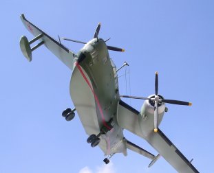
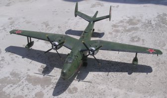
Model-wise I have already built up two HU-16s, two Catalinas and a Widgeon and these form a colourful section in my model collection. However, I have never been so much intrigued on making a model of a flying boat as when I received a 1:72 scale model kit of the VEB "Madge" Beriev Be-6. Although the list of flying boat scale models is quite appreciable, those Russian ones are very few. The Be-6 was therefore more than welcomed. THE
'VEB' OR PLAYCRAFT BERIEV Be-6 KIT The
1:72 scale model of the Be-6 is mainly moulded in white plastic. This is of a rather brittle type of plastic as
the kit I possessed was fractured from two places in both the fuselage and main
wing parts. But this is of no concern as the pieces welded together
quite effectively with
liquid cement. Some parts such as the propellers,
tail barbette, guns, aerial masts are moulded in black plastic.
These had a crude
appearance but
with little effort the propellers and the
cannon barbette can be salvaged and used on
the kit. I
elected to do the later version of the Be-6, which was mounted with a Magnetic Anomaly Detector
"MAD" "stinger" aft of its tail. This meant
that the aft part of the rear fuselage had to be modified and rebuilt completely, different from that supplied with the kit. We come back to this at a later
stage.
The
transparencies supplied are in very clear plastic. In all there are a
total of 38 components excluding the 2-part stand, which I always discard anyway. There is an
assembly drawing which makes construction straight forward if one desires to do the version
as issued. However in my opinion the kit was very basic and fell short of my expectations. This turned out into a project that model-wise
required a lot of work to turn it into an accurate scale
replica of the real flying boat. Certain areas such as the cockpit has no provision
of any detail and one should not be deterred
from manufacturing a cockpit floor, bulk-head, instrument panel, a couple of seats, control
columns, control foot pedals and other de-tails
as one desires. The ailerons, which are designed
to be moveable, leave an unrealistic gap when raised or lowered so it
would be best to fix these in place permanently. At the lower part of the hull there is
a rectangular slot into which
the stand will fit. This needs to be trimmed
and filled. Over
the years I managed to acquire copies of LETECTVI
+
KOSMONAUTIKA, a
Czech
magazine that goes back to 1980. This contained an article, which related to updating the
Be-6 kit. Pages 290 and 291 produced a side elevation
of the fuselage and wing plans and on
pages 374 and 375 there is an accurate "stinger"
MAD boom drawing. More recently more
accurate material in the form of photos started to emerge and reference to these enabled
me to produce accurate revised scale drawings
of the undercarriage beaching gear. Adding the beaching gear to
the kit produces a more impressive
and realistic appearance.
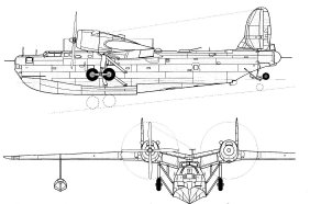
HISTORY
OF THE BERIEV Be-6 The
Be-6 is a large maritime reconnaissance and bombing flying boat that
flew for the first time
in 1947. An all-metal high-wing monoplane that was powered by two 2000hp Shvetsov
ASh-72 radial engines. Until early sixties it was still in service and
was relegated to fishing patrol and protection duties with the Soviet
Navy. It is the only Russian flying boat of post war design to have attained quantity production. The
Be-6 are known to have formed part of the North Fleet since 1953 in both the rescue form
that was based at Poty, and others belonging
to the 318th Independent ASW Air Regiment
at Donuzlav in 1967. Other Be-6s were based
at the hydrobase in Taganrog. The Be-6 left
a mark in the maritime history of the Soviet Union and was the
forerunner to other important projects that were to come out of the Beriev line
that followed. The Beriev ventured on patrol,
maritime recce, ASW duties till early 70s. Others remained in service
on transport or fishery protection duties into the late 70s. ARMAMENT Defensive
armament on the Be-6 ASW "MAD" version comprised twin NS-23, 23mm cannon
in a remotely controlled dorsal barbette and a single NS-23 cannon
installed in the bow turret.
The Be-6 carried sophisticated equipment, which included a retractable
radome aft of
the second step. At a later stage it had a redesigned
nose without cannon equipment. The Beriev carried a heavy offensive load comprising
a variety of combinations of mines, depth charges and torpedoes on underwing pylons
located outward and inward of its engines. Typical
bombs carried on underwing pylons as the
250Kg bombs, shown in sketch "C".
Other typical
loads include AM-1000 mines, depth charges
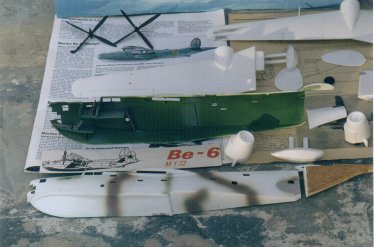
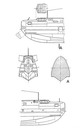
and type 45-36 ABA torpedoes. KIT
MODIFICATION & ASSEMBLY The
model of my Be-6 was converted to the later
version, which involved modifying the rear end
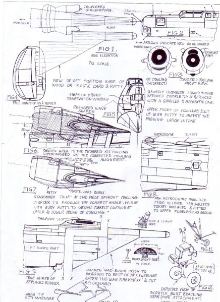
of the fuselage to take the MAD Sonar equipment, which is shown
in FIG. 1. part of the rear end of the fuselage and sonar combinations
were produced out of yellow pine.
This is a soft, easy to work,
wood, which does not warp with
time and
is normally used to make master patterns
for production castings. Section templates were made out of cardboard using
the plan and side elevation drawing
in FIG.1. Producing this component
took some time. In the end,
after it was carved close to the shape
required, it was given two coats of sanding sealer, allowed to dry
and sanded down to shape.
The
next step was to place the fuselage
halves, part I and 2 together, securing them temporarily with
tape from three places. This allowed
marking and cutting along line "X-X"
shown in FIG.9. This was then cut with an Xacto knife and
fine saw. The horizontal part was
the tricky bit. This was scored several
times over using a sharp modeling
knife until it broke away gently
from the corresponding half of
the fuselage, one at a time. The end
bit of the kit fuselage was discarded.
A medium file brought down
the desired joint preparation so
that there is an even and corresponding
joint between the fuselage
section at "X-X" and the wooden
shaped piece at "X-X"
that contains the
"MAD" boom.
The
kit first appeared on the market
over 20 years ago and was then a reasonable product. With the advent
of the breakdown of the Iron Curtain certain details on military
aircraft started to appear in form
of photos, accurate drawings, data.
etc, certain areas on the kit such
as the portion ahead of the cockpit,
aft of the cockpit, wave guard fairing, position of antenna masts,
grossly raised panel lines, shape
and size of turret/barbette needed to be looked into and each
item is rectified with careful reference
to the new material. Though small
items these appear to be, it is
surprising what improvements these will bring to the "end-product"
appearance.
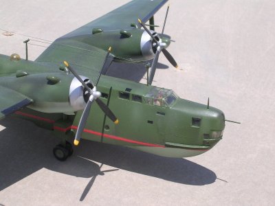
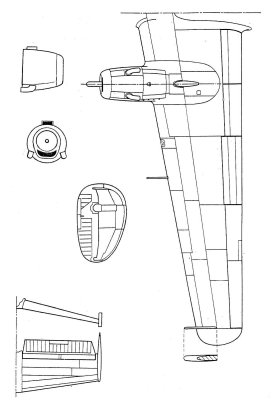
While the kit is still in pieces, it is important to mark, drill and shape the 15 porthole windows that are scattered throughout the length of both fuselage sides. The location of these is identified with careful reference to the 1:72 scale drawing shown. Some of the existing ones may need to be blanked over with plastic card and replaced with others of the correct shape and at the right place. At this early stage the mainplane and tailplane parts are glued together and allowed to set. A major fault in the kit lies with the angle of the centre line of the engine cowlings with the horizontal. A quick check with FIG.6 or reference to the 1:72 scale plan side elevation will reveal the new angle of elevations. This needs to be so much inclined so that when viewed from the side, the lower part of the cowling front rim is 5mm higher than the uppermost level of the fuselage. This is illustrated clearly in FIG.6.
In order to reproduce this
inclination
to the kit parts this has to be carried out as follows: (A) Remove the exhaust pipes, which are wrongly placed at the cowling joint line. The huge lower intake is also filed off completely. See FIG.3. Replacement small intake ducts and new position of exhaust pipes are needed. (B)
Blank
the rear end of the cowling (parts 14 and 15) with a 25mm round
plastic card. (C)
The upper edge of the cowling on wing (parts 3 and 4) are filed 2mm
at the joint so that when parts 14 and 15 are fitted these have a corrected
inclination. (D)
With reference to FIG.7, the cowling parts are now joined together
noting the new angle of inclination and also the joint is staggered
by 3.5mm at the upper and lower rim of the cowling ends. (E)
Once this has dried out, the stagger is built up with putty. This is
allowed to dry, reshaped and faired over. A somewhat tedious operation
but in the end it brings a satisfactory result. FIG.7 indicated the
built up areas, which are shown in shaded lines. (F)
All along the upper area of the cowling is built up with putty to produce
the upper air intake, which was non-existent in the kit. FIG.3 shows the
incorrect cowling front as compared to the new one. Note also the
upper area of the kit cowling that needs to be filed (shown in
dotted lines) before the putty is added. This will be the lower in-take
front/wall. (G) Having built up and reshaped the cowling, a small air intake is added to the lower cowling front as per drawing. The air intake is made out of a rear part of a small fuel tank (2 in number) found in the spares box. (e.g. AIRFIX Fiat G91 wing tanks). The upper exhaust pipes are produced from sprue which are shaped and hollowed out at one end. CONVERSION
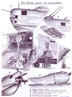
TO THE 'MAD' SERIES Before the two fuselage halves are
permanently joined, any cockpit detail as mentioned earlier is completed.
Sketches show shape of pilot and
cockpit seat, control 86
column and instrument panel. I added
two crew members as it gives
a scale indication and more life
to the completed model. The drawings
show all the identifying features of the Be-6 to convert to "MAD"
version series. This merely
required cutting, filling, scribing
and reshaping operations to reproduce them in model form. Vac-forming
of the dorsal astrodome was
essential using the male/ female
acetate technique. This is of a smaller diameter at the root and
the hole that exists on the fuselage needs to be blanked and re-bored
accordingly. The 23mm cannons shown in
FIG.2 & FIG.8 are made out of 1mm
diameter injection needle steel, which are cut to the required length
as to leave 12mm barrel length. Three in number are required,
one for the front, and two for the dorsal barbette.
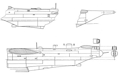
After the kit is completely assembled, with the major components put together, the various aerial masts and small intake scoops on the fuselage are added and the joint lines of the rear modification components are sanded, refilled and sanded gently until a smooth satisfactory finish is obtained. The two supporting struts of the floats needs thinning down their sections when viewed from front as per wing float scale drawing.
The hull rudder supplied is replaced with one from plastic card and correct outline and relocated aft of the hull structure as shown. FIG.5 shows the reshaped wave deflectors/guards. This is done by reducing the oversize ones integrally moulded on the fuselage front, and also by thinning down this section with a scraper running down the remaining length. An observers front nose window is added to conform to FIG.5 and the scale plans. Wing tip ECM antennae are added - see FIG. 10. These are made from 2mm thick by 3.5mm wide plastic card, which protrudes 6mm ahead of the leading edge.
BEACHING
GEAR Having
done all the extra work to improve the kit, then building up the
beaching gear becomes imperative.
The scale drawings show the correct size of the details to produce
the beaching gear and FIG. 11 depicts an exploded view of
the aft wheels construction; FIG. 71 shows the main wheel beaching
gear along with parts to form the floats. These are made out
of sprue and plastic card. Two wheels, 14mm diameter and 5mm wide are attached to the assembled structure on each side. The
smaller rear wheels are 8.5mm diameter
and 3mm wide. I found that for the main wheels, those coming from
1:96 scale REVELL B-57 Canberra
kit are most suited, failing
this one can produce a single accurate
wheel and cast 3 more out of
resin using two part core and drag
mould technique. The kit provides
one leading edge aerial antenna.
The location is correct but the
aerial mast was discarded and replaced
with one made from a pin. This
is repeated to the other wing as
most of the photos I have seen carried
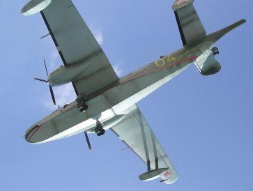
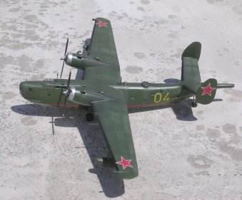
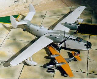
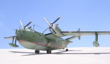
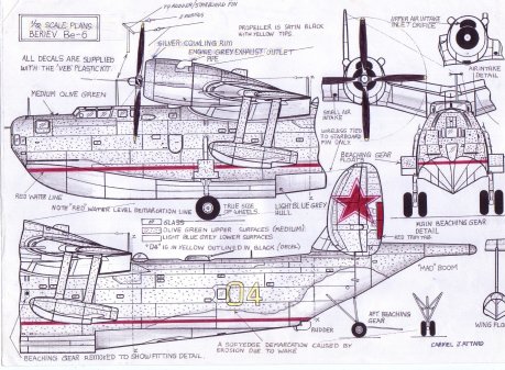
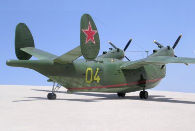
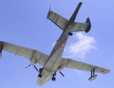
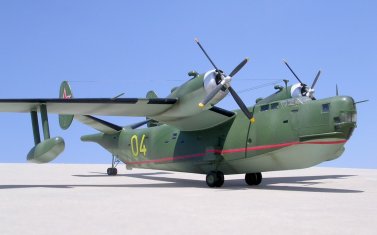
one antenna on each wing. COLOUR
SCHEME A good number of Be-6s were finished in olive green upper surfaces and light blue grey undersurfaces. On my model I applied two shades of olive green, one lighter than the other to bring out the weathering effect. The kit is supplied with a reasonable quality decal sheet. These only needed the transparent film trimmed off at the periphery otherwise the large red stars makes the kit look complete. A large yellow number "04" which is neatly outlined in thin black was ideal for the exact version 1 have made. A long red water line decal trim was carefully applied to the hull. Other weathering effect was added by airbrushing engine grey to areas aft of the exhausts and engine cowling front. Cowling rings were completed in silver paint. A soft edge merging separated the upper olive from the lower blue/grey finish.
Alternative
fuselage identification numbers
carried by various types of
Be-6 have been noted on photos.
These include 1, 02, 07, 14, 11,
15, 10, 5, 47 and 24. Some early
Be-6 and also others that went
late into service were finished light
grey overall. The Peoples Republic
of China also had Be-6 in service on maritime patrol. A particular one
was in overall grey finish,
which carried large red identification number 89706 on the forward
fuselage beneath the cockpit
and the red star and bars in all the appropriate positions. Apparently the Chinese went further in developing the Be-6 as the one being
referred to is powered by a pair of turboprops in place of the
bulky radial engines. The turbo props
closely resembled the Ivechenko
AI-20 powerplants normally
seen on the II-18. The
VEB Be-6 Madge may indeed be a challenge to construct, modify and add detail to, but in the end it
is very rewarding with a pleasing result,
producing a Soviet aircraft
that for many long years we
knew little about, until now...............
REFERENCES Observers
World Aircraft Directory - William
Green L&K
issue No.8. 1980
Photos
in author's own collection. |