| ggg |
|
Guest
article by Glenn Ping
This
article features the
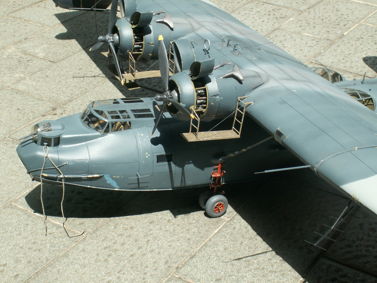
magnificent Tigger Models 1/32 scale Consolidated Catalina vac-form
kit, the very same kit as advertised in the SEAWINGS Flying
Boat Shop today, originally conceived, molded and released many
years ago under the banner of I.D. Models by master-modeler Doug
Feeney as part of his then (very) revolutionary and growing 1/32
vac-form kit range. The molds languished for many years until
recently, when talented scale modeler John 'Tigger' Wilkes acquired
all the molds of the range and began re-issuing them. The Catalina,
together with a large number of the other members of the range which
also includes the Short Sunderland flying boat, an example of which
is currently being built by SEAWINGS and is featured as a
step-by-step guide in the SEAWINGS BLOG (accessible from the
link on the front page of this site) are the two flying boats in the
range.
Potentially
daunting to many due to its its sheer size and the basic - yet -
accurate shaped moldings, in the hands of a talented and experienced
scale modeler such as Glenn Ping the kit comes alive!. Read on to
see just how to get the best out of this kit and produce a
magnificent example of the scale modelers art...............
(Click
on the pictures to see the full size image)
|
 |
|
|
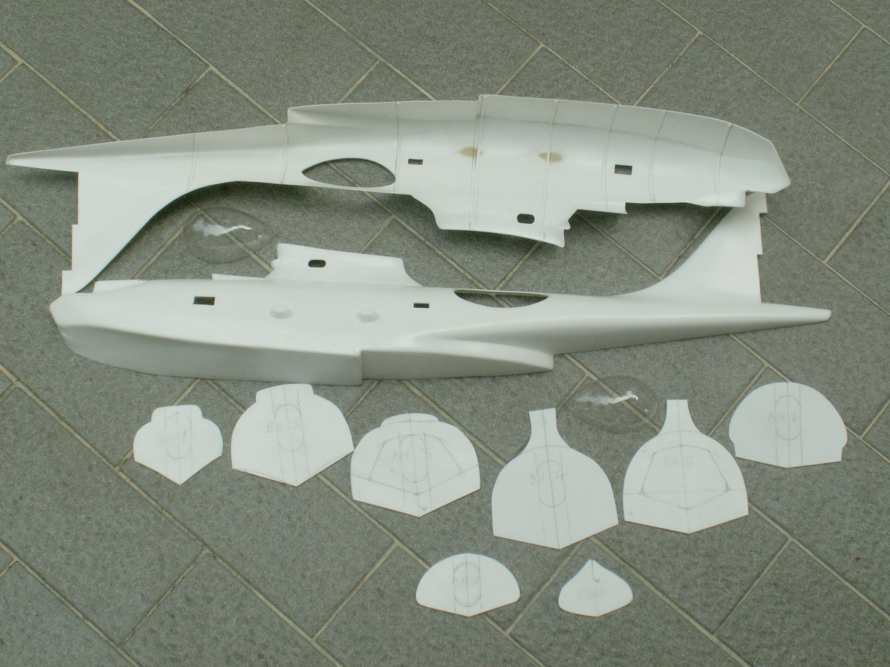
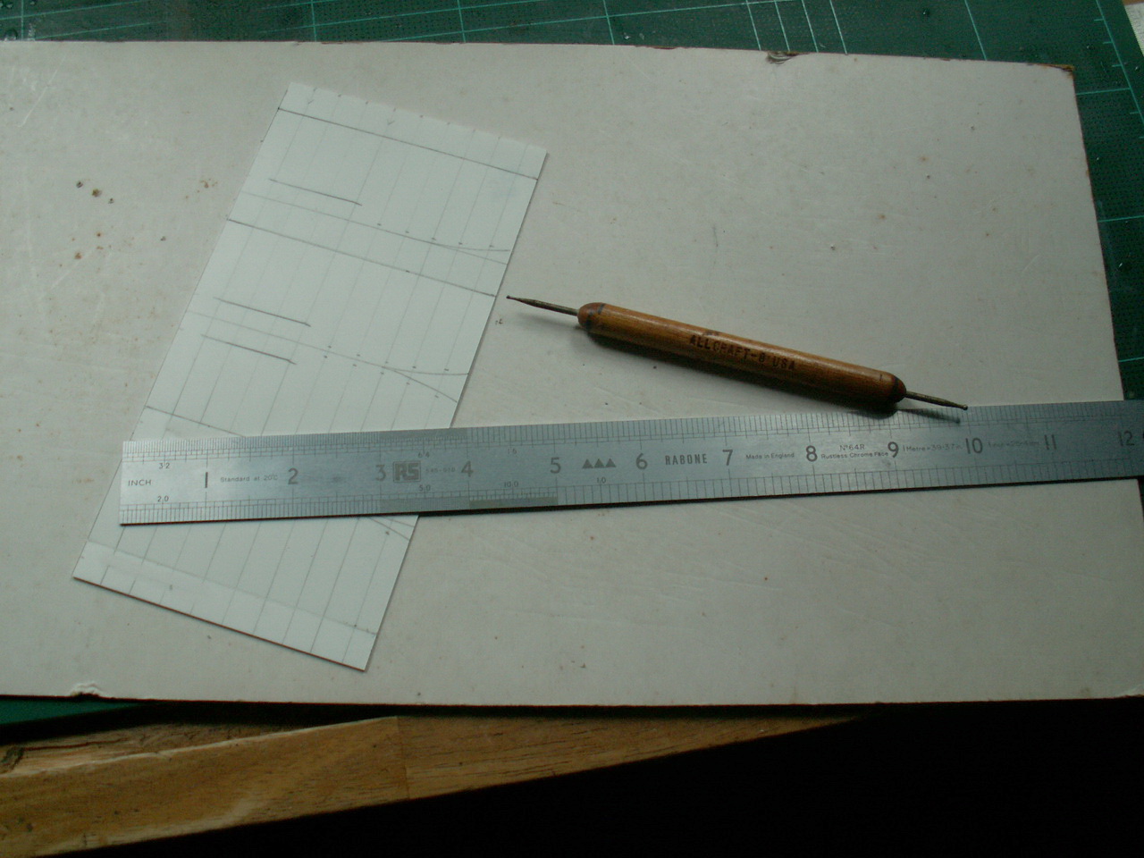
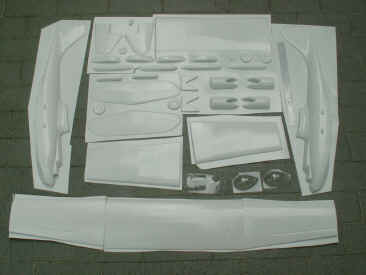
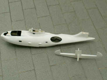
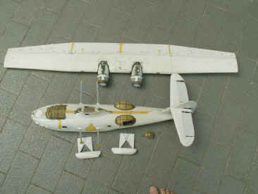
| Now
that most of the old I. D. vac-form models are available again under the
name of Tigger Models, I decided that I would like the 1/32 scale Catalina
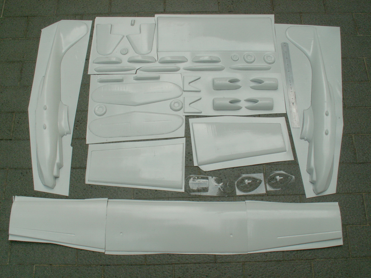
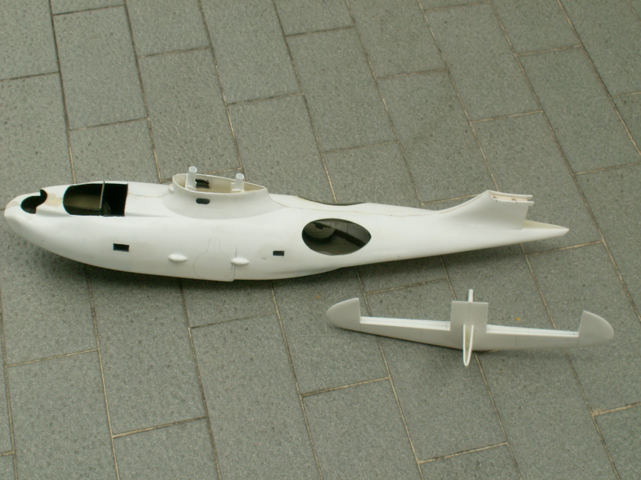
kit. When
it finally arrived, I opened the big box and laid the pieces out, as in
the photo at left. Note
the 12 scale ruler on the right-hand side of the picture, this kit has a meter long
wingspan! |
|
| g |
| Right,
lets make a start! First the Wings |
| g |
  |
| g |
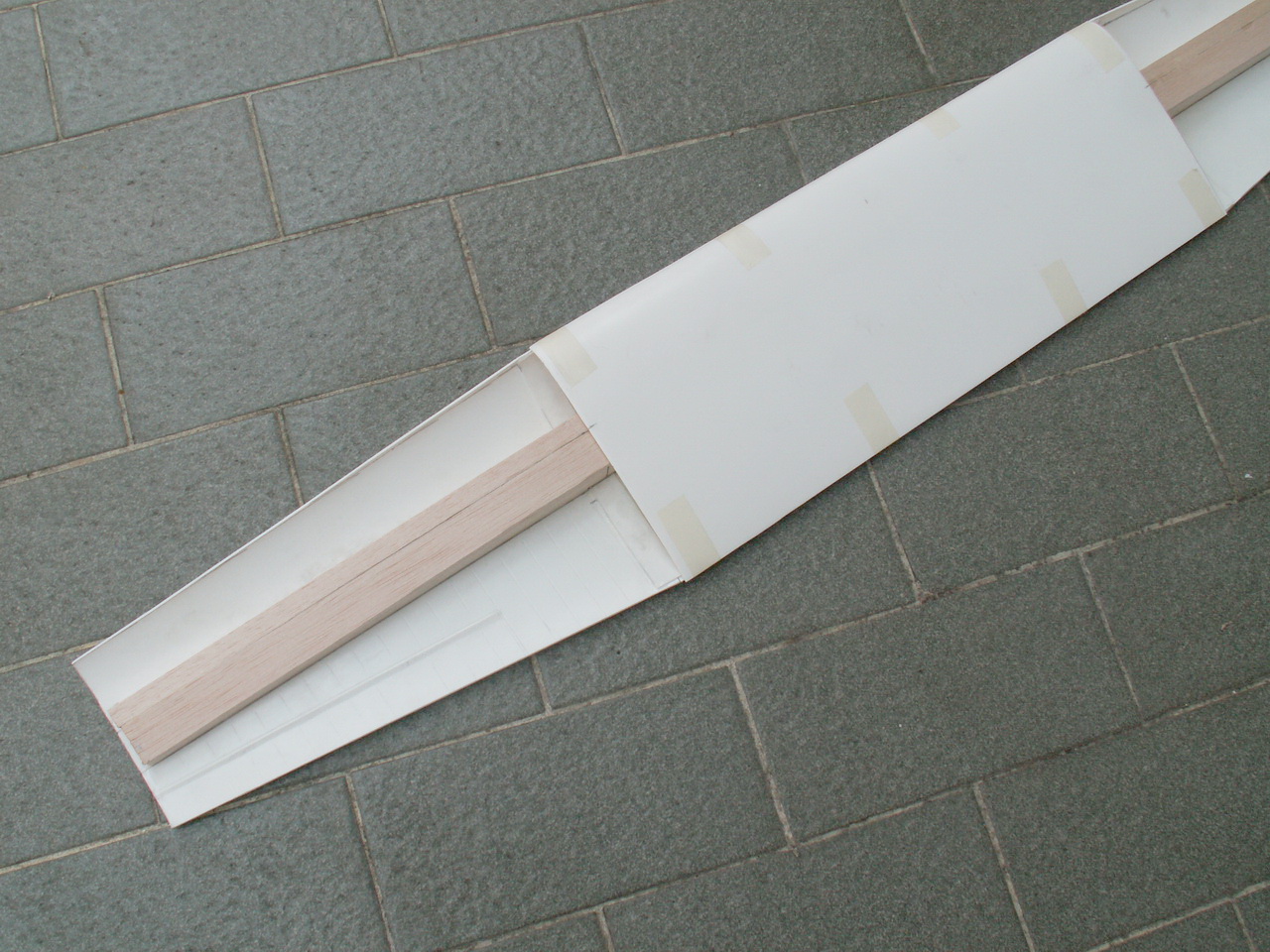
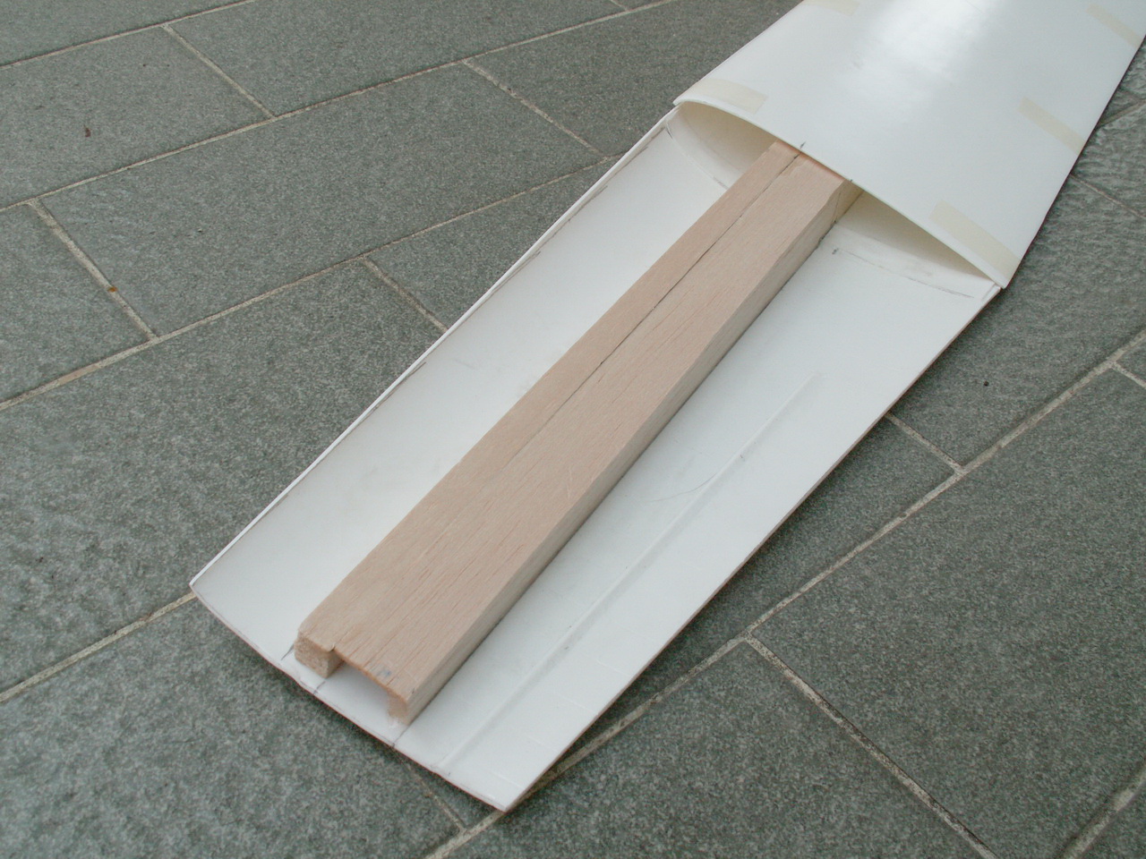
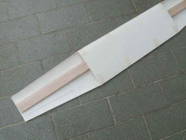
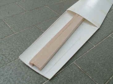
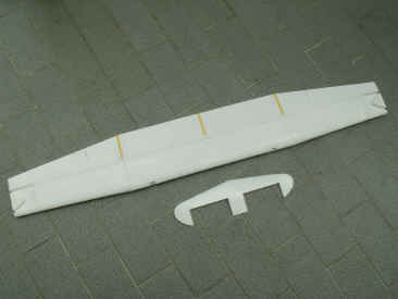
| As the wings have no dihedral on the outer panels, I could make a ¼
thick balsawood spar which stretched the whole wingspan, plus another
piece which went over the metal/fabric joint of the wing, this was fixed
down using adhesive (superglue) with a few squirts of
kicker. In
most of the construction of these vac-form kits, I use cyano
with kicker as an adhesive and only use liquid polystyrene cement on
some of the smaller parts. By using cyano, construction can be quite
rapid, as you dont have to leave things overnight to dry. |
| g |
 |
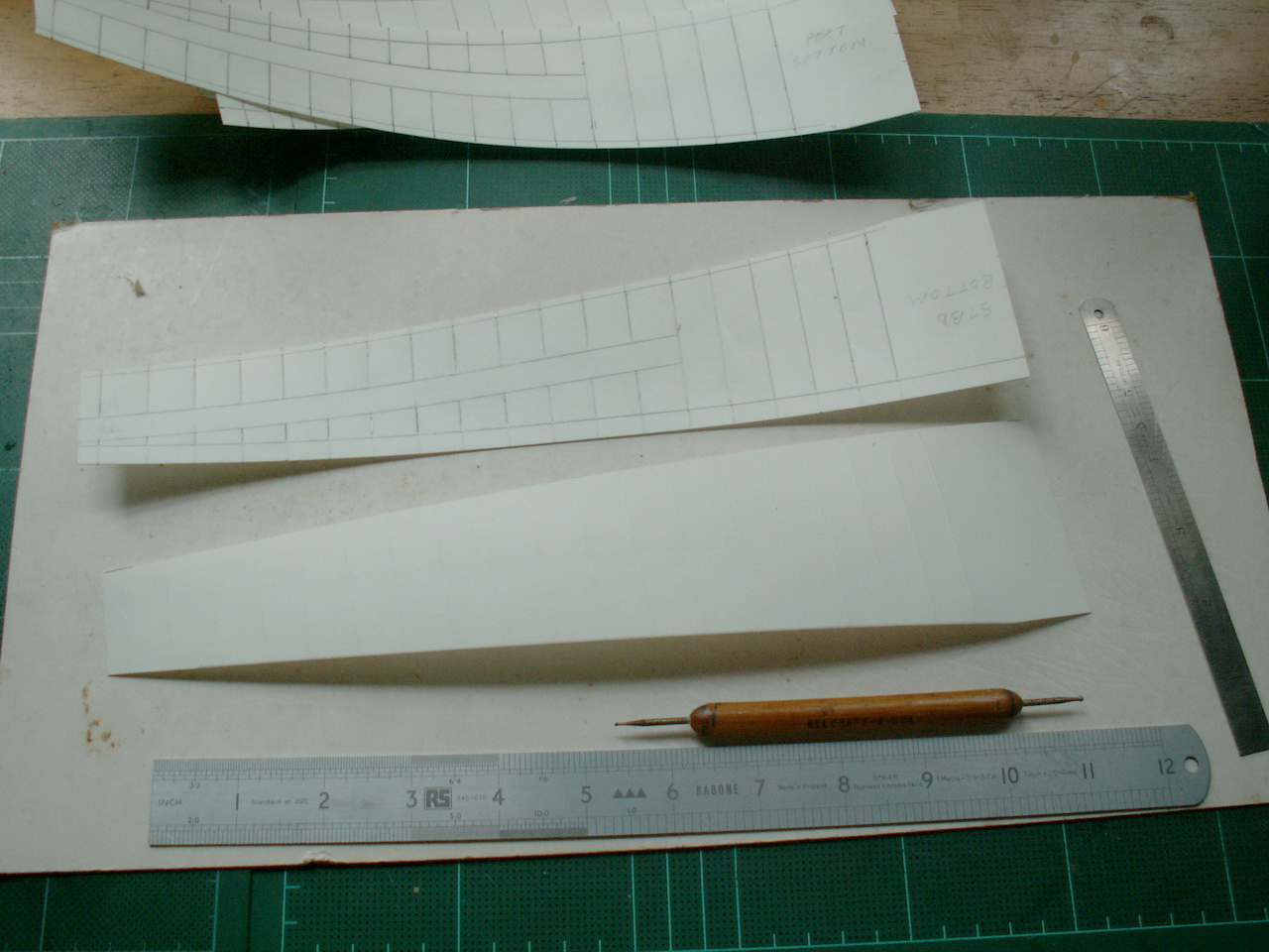
| Left:
I
was not happy with the moulding of the fabric areas on the model, so
decided to replace them with some embossed 20thou plasticard sheet. |
|
| g |
|
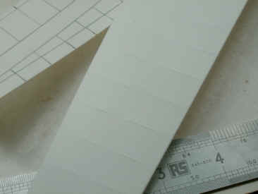
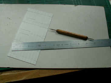
Shown
above, the outer wing skins are being embossed. The ribs have been
traced from the plans and transferred to the skin. Rib lines are then
embossed onto the skin using a steel ruler and an embossing tool. The
embossing tool can be seen at
the bottom of the photo and is actually a steel rod with a small ball on
the end, fitted into a wooden handle. Mine is double-ended with two
different sized ball ends.
When
embossing, the skin must be laid on some card which has a little bit of
give in it, Ive found the card that is used to border
photos/pictures in frames, is ideal.
|
| g |
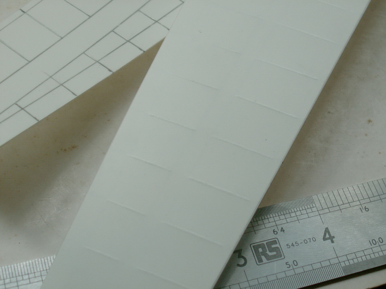
| Right:
you can see one of the skins turned over to show the embossed ribs. This
process was done to the whole rear portion of the wing, elevators and
rudder. |
|
 |
| g |
 |
 |
| g |
|
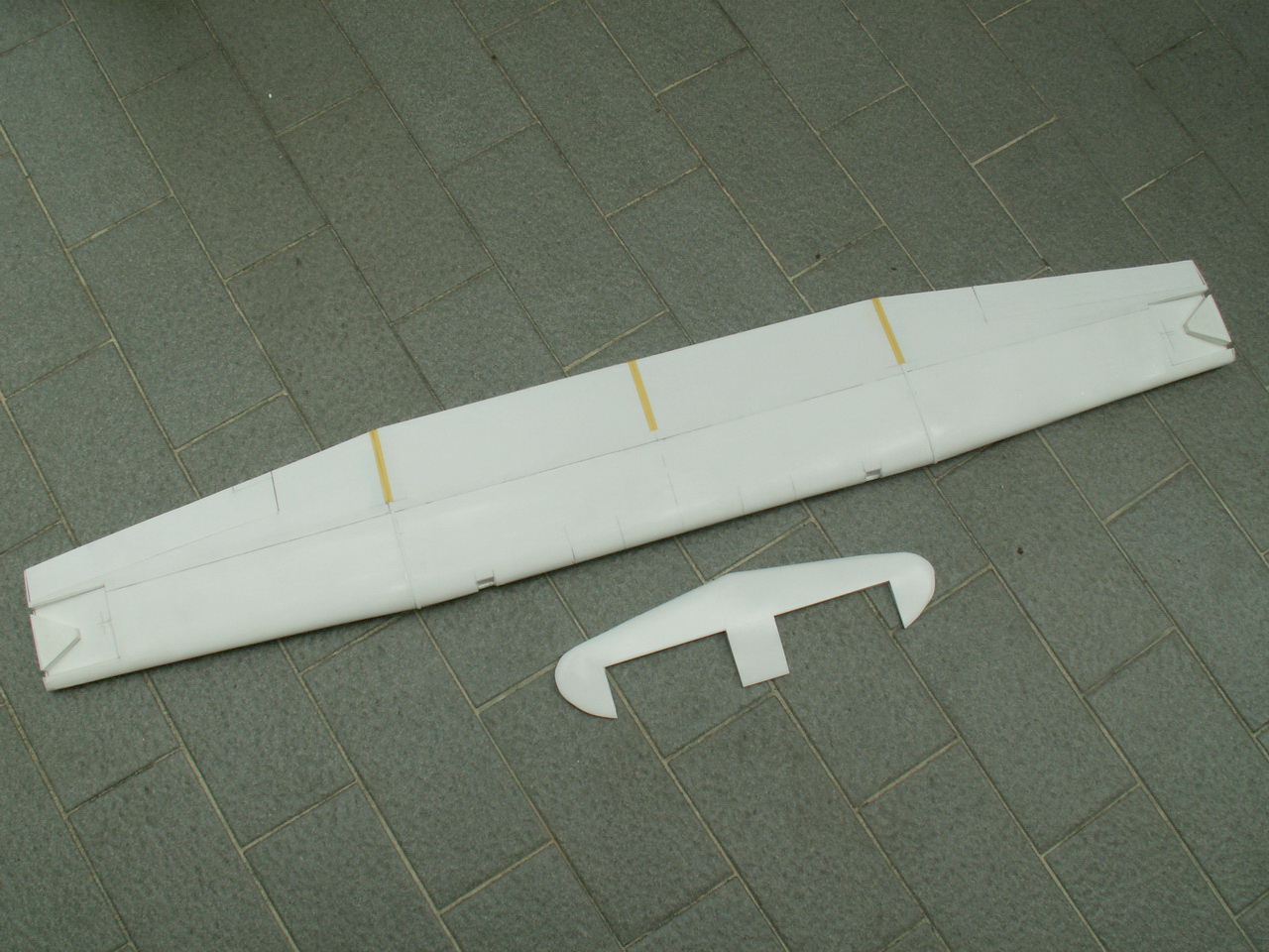
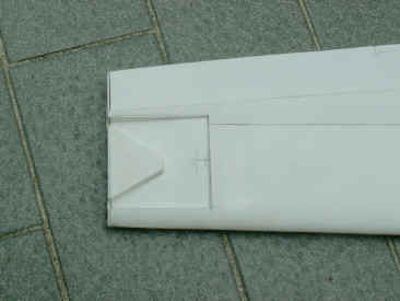
Moving
on a bit now, in the photo above here we have the completed wing and tailplane, minus the
elevators which have been cut out and replaced with embossed 20thou sheet,
these will be fitted later. |
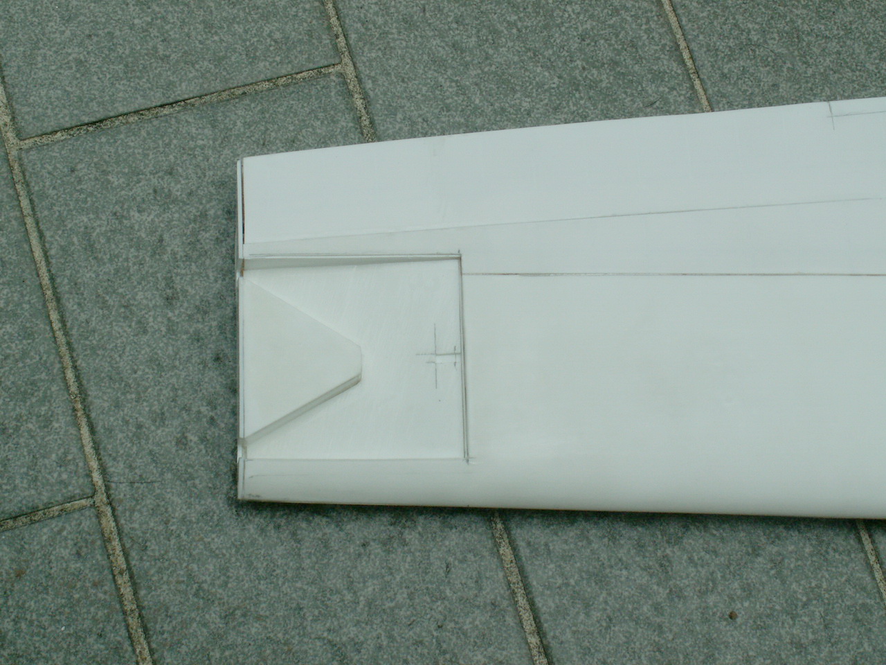
Above
right,
on
the underside of the wing, the recesses for the folding floats are cut out
in the outer wing panels and boxed in. |
| g |
| The
Hull
and Internal bulkheads |
| g |
|
I
then turned my attention to the fuselage. The mating edges were filed down
until the correct width was obtained. The cockpit canopy is used as a
gauge to get the width just right. I did find the nose area, forward of
the canopy, to be too wide according to my drawings, so a little
adjustment to the mating edges was needed, some squeezing will be required
when the fuselage halves go together in that area. Cutting
out the rudder was done using a sharp knife, as were the windows and rear
fuselage canopies. |
| g |
 |
| g |
| As
seen in the photo above, a series of bulkheads were made from 40thou plasticard. To obtain the
correct fuselage profile for the bulkheads, I used a strip of multicore
solder pressed into the fuselage and the result was then transferred to
some thick card by drawing round the edge, cornflake boxes give some of
the best card for this use. After the shape has been transferred, its
cut out and tried against the fuselage side for any errors. If all is OK,
the shape is transferred to a sheet of 40thou plasticard and then the card
is flipped over to give the other side of the fuselage. This method only
uses pieces of card for adjustment and not the plasticard. |
| g |
|
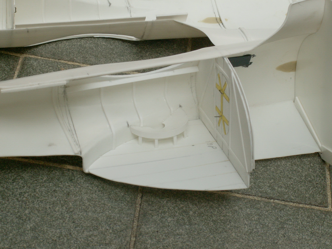
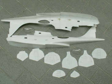
Below:
once
the bulkheads were finished, there was the option of opening some of the
hatches (doors). I decided to half open the one behind the pilots
cockpit and leave the rest closed. These hatches are made from 10thou
plasticard. After that was sorted out, I attached the bulkheads to the
port side of the fuselage and added the floors to the cockpit and waist
area. As the windows are small in the engineers station and along the
fuselage, no detail can be seen from them, so I decided to paint the
insides gloss black. The same thing applies to the area behind the
pilots cockpit. |
| g |
  |
| g |
|
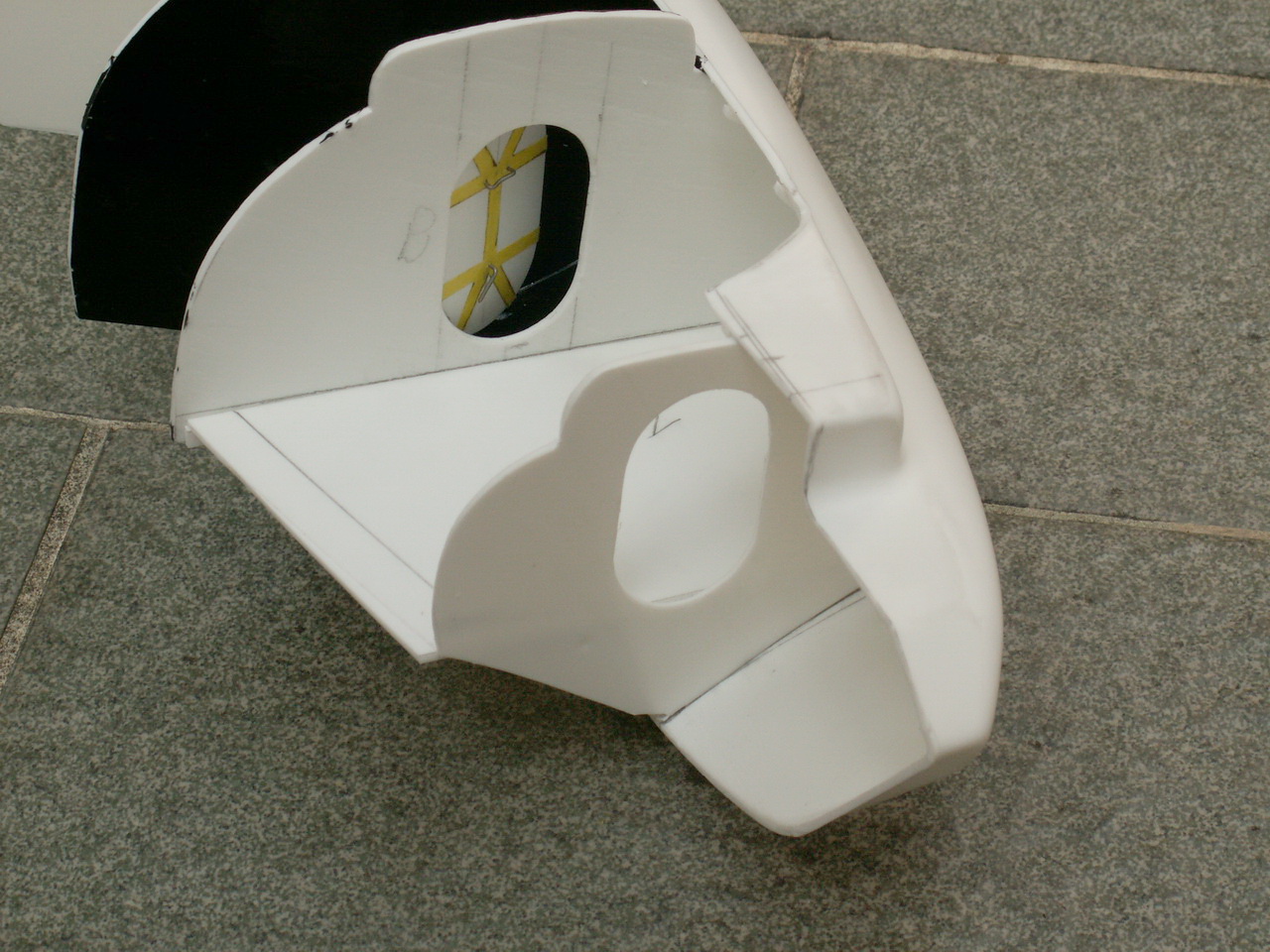
Consideration
must now be given to the wing attachment. A strong joint is required on
such a large wing. My solution to this was to fix two tubes, vertically,
in the engineers compartment, which then would fit tightly into two
more, slightly bigger, tubes in the wing.
The
fairings for the wing struts were filled with epoxy putty to strengthen
this area as can just been seen in the photo, right above. An extra layer of plasticard (40thou) was also fixed to the
inner fuselage side where the beaching gear would eventually attach, the
same thing applied to the fuselage rear.
Strips
of plasticard 1 long and ¼ wide were fixed along the fuselage joint
to give more area and make for a stronger joint when the fuselage halves
come together. Quite
a lot of detail has to be put into the waist area, as much of it can
be seen from those large canopies.
|
| g |
 |
| Left:
less
detailing can be put into the pilots cockpit and nothing in the nose
gunners compartment, as once the guns are in, little else can be seen. |
|
| g |
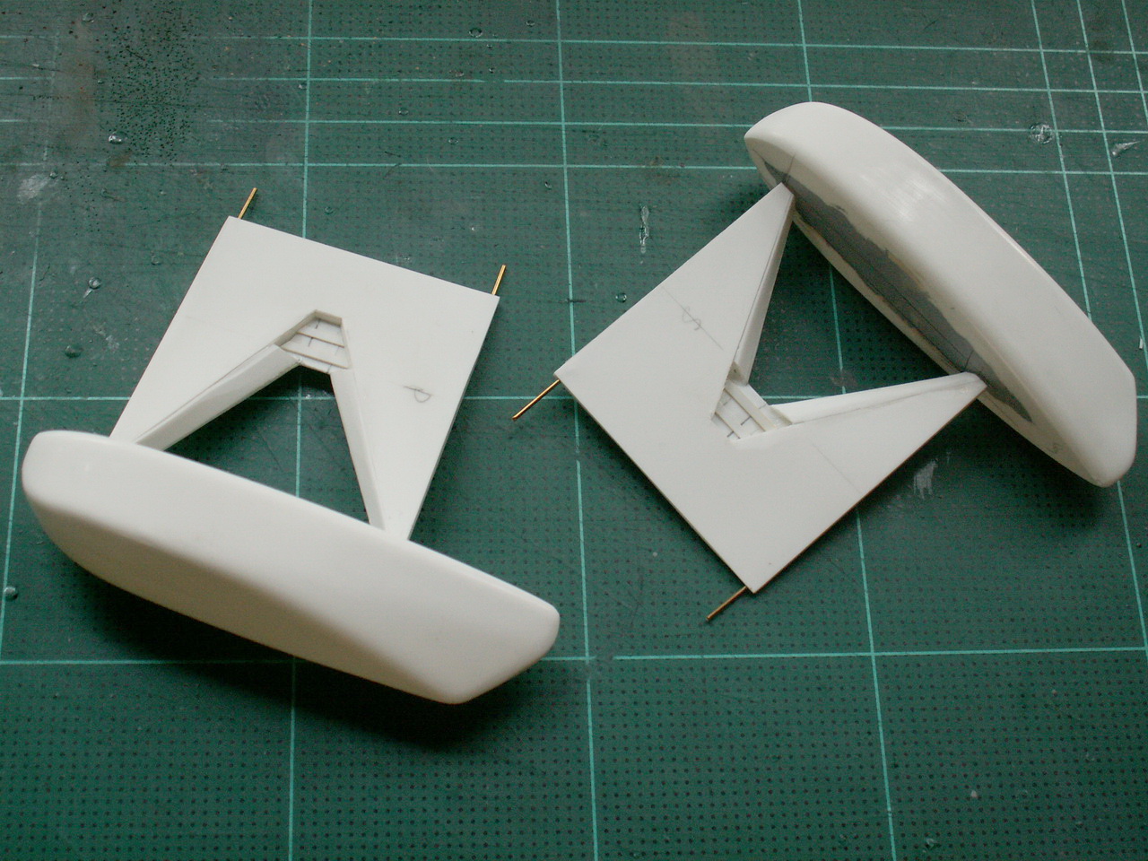
| The
Wing-Tip Floats |
| g |
| Right:
To
make a change from the fuselage, I had a go at the wingtip floats. They
were quite easy to construct, but I had to remember to put some brass rod
into the strut arms, as can be seen in the photo. Rivet detail was done
with a pounce wheel. After this photo was taken, I added some hold
down rings to the front and rear of the floats. |
|
|
| g |
| Engines
& Exhausts - Bought in and Scratchbuilt |
| g |
 |
| g |
|
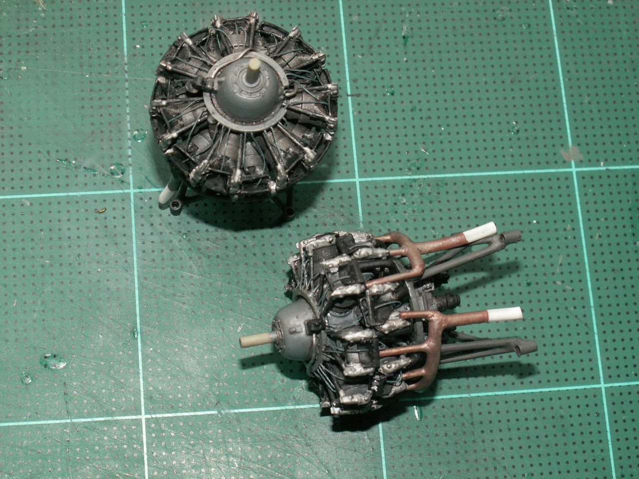
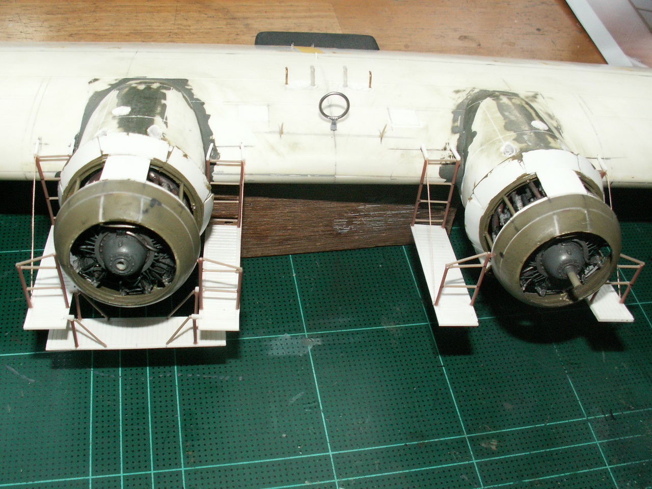
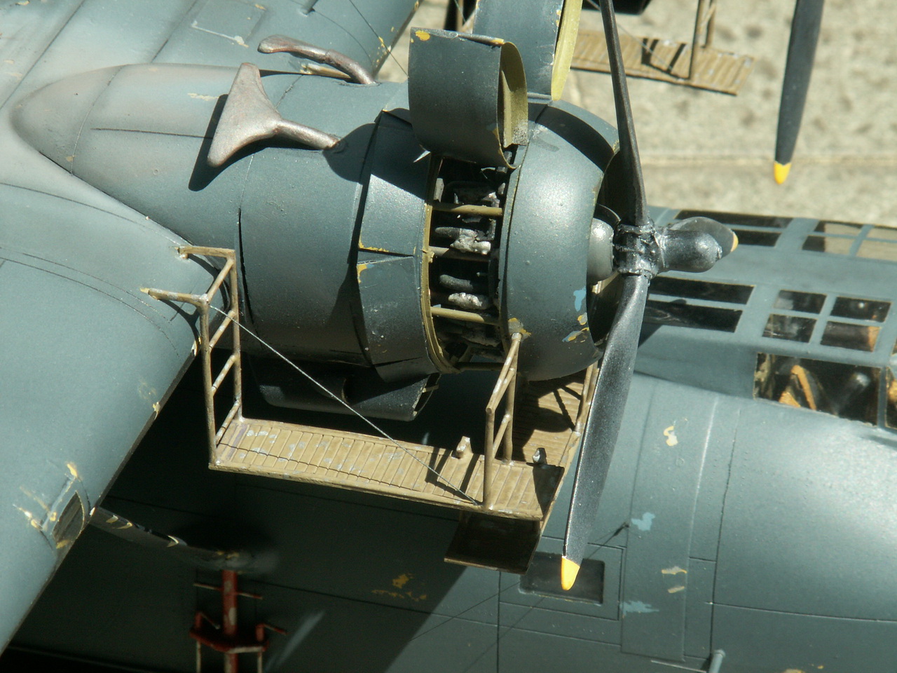
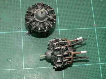
Above:
As
there are no engines supplied with the kit, I bought a couple from the
excellent Vector range. These are little models in themselves and cry out
for detail painting. I added the plug leads to mine, 28 on each engine!
The engine bearers were made from plastic rod and tubing. Heres
a word of advice to anyone wishing to add plug leads to these engines.
Start
by affixing the leads to the cylinders and THEN to the distribution ring.
I did mine the other way round and it took ages and a lot of cursing.
The
exhaust pipery was made from thick multicore solder, cyano being the
adhesive.
My
recipe for painting exhausts (plus collector rings), is first a coat of
Humbrol 113 Matt Rust, which is then drybrushed lightly with Humbrol
16 Metallic Gold. This in turn, is then drybrushed lightly with Humbrol
56 Metallic Matt Aluminium. Once that is dry, a pencil is scraped
across some sandpaper and the resulting powder is gently brushed over the
whole of the exhaust. A little pale brown, Humbrol 121 Matt Pale Stone, or
Humbrol 148 Matt Radome Tan, can be drybrushed to the end of the exhaust.
|
| gg |
 |
|
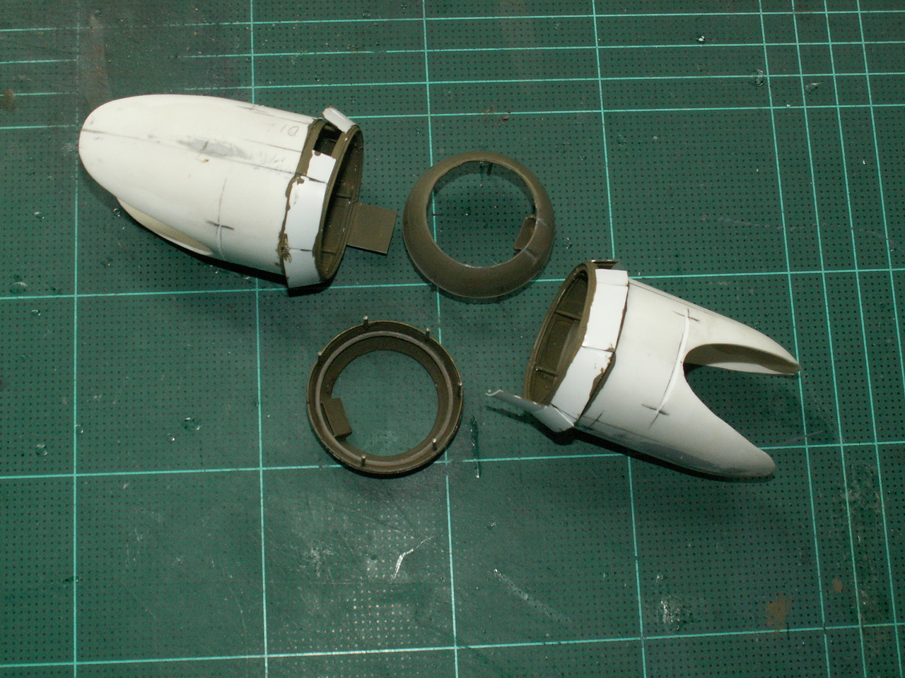
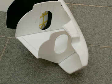
Left:
I
was not happy with the shape of the front of the engine cowlings and
replaced them with some resin ones copied from the Revell Beaufighter. The
nacelles were built up and the cutouts for the wing were achieved by trial
and error.
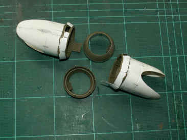
Rings
were cutout from plastic phone cards and rims fitted, the cooling gills
then being built and attached to the rims.
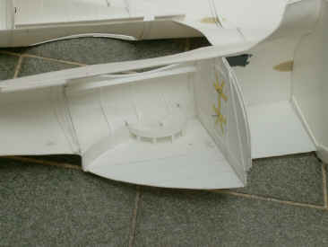
As
I was going to display the engine cowlings open, I used some small
diameter plastic rod to attach the cooling gills to the nacelles and the
same to attach the cowling front to the gills. This was a mistake, as the
thin rods kept breaking, brass rod would be the ideal solution here.
|
|
| g |
| Returning
to the Hull........ |
| g |
 |
| g |
|
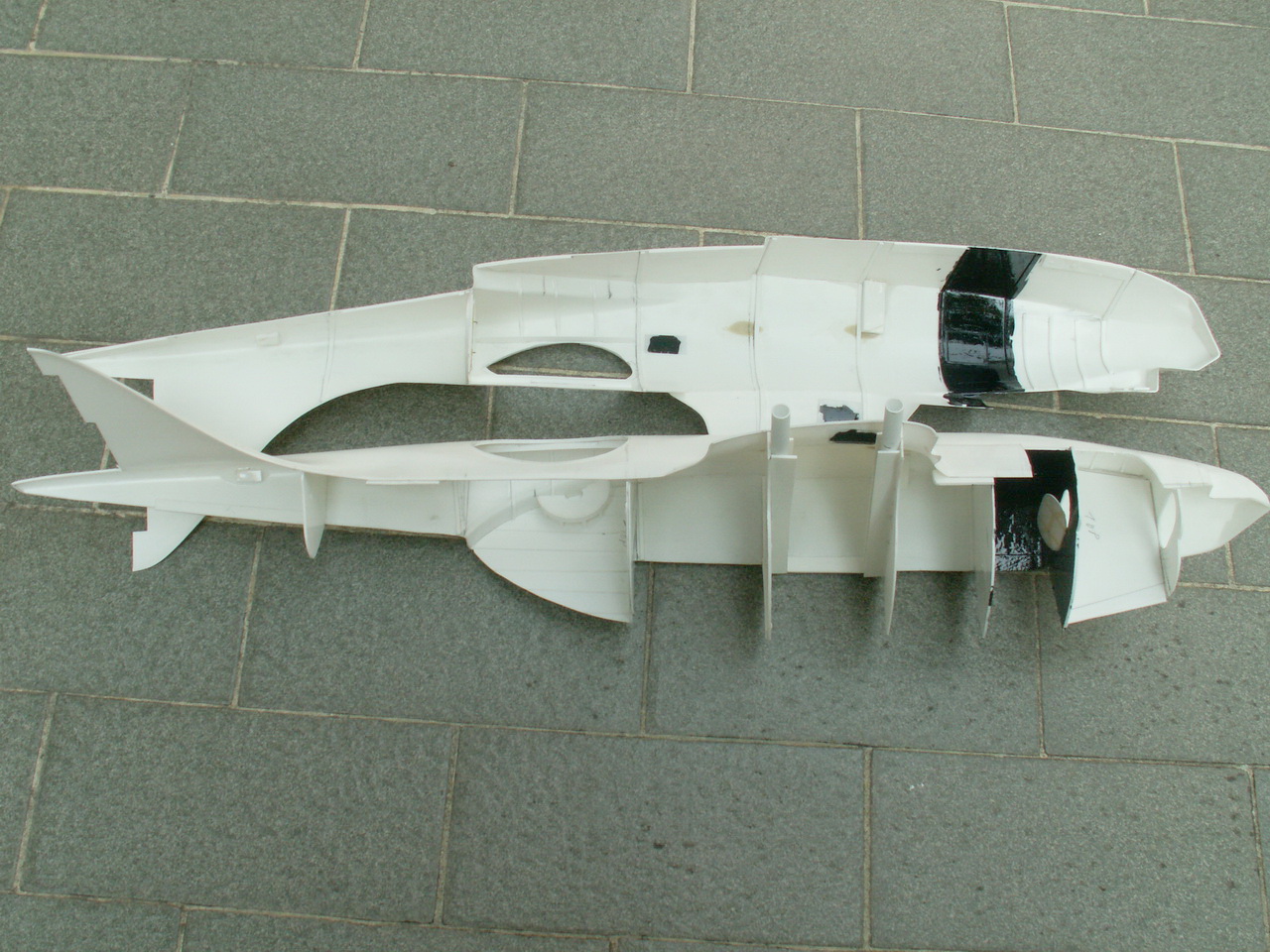
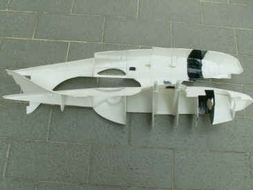
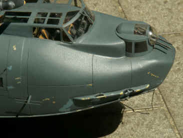
Back
to the fuselage now. The
interior areas were painted Humbrol 159 Matt Khaki Drab and were
chipped and scraped with Matt Aluminium to give them a used look.
At
last, the fuselage halves came together, with the aforementioned squeezing
required at the nose area, as seen in the photo above. As
you can imagine, a lot of jiggling was required to get all the bulkheads
aligned, harsh words were spoken, but it went together in the end. The
joint was then cleaned up, with a few bits of filler here and there, till
it looked about right.
Now
came the bit I really hate panel lines. All Ill say is that it was
done! The same can be said about the riveting. As
the model Im depicting was de-converted from an amphibian, huge patch
panels were placed over the mainwheel housings, these were reproduced
using some 10thou sheet.
Cutting
off half the fin to take the tailplane was next on the list. This took
some time to get the angle of the tailplane just right. Two pieces of ¼
balsa were fixed into the fin base to form a good strong anchor point for
the tailplane. Holes were drilled in these pieces to accept two plastic
tubes which had been glued into the tailplane and through into the top
portion of the fin.
The
interior portions were then given a watercolour wash of a mixture of
Paynes grey and burnt umber, to
darken the recesses and tone down the scratched and chipped paint.
|
| g |
 |
|
Left:
Moving
on, embossing the elevators and rudder was the next job. Exactly the
same method as embossing the main wing was used. Having
had enough of the main model for the moment, I thought I might try my hand
at making the beaching gear............
|
|
| g |
|
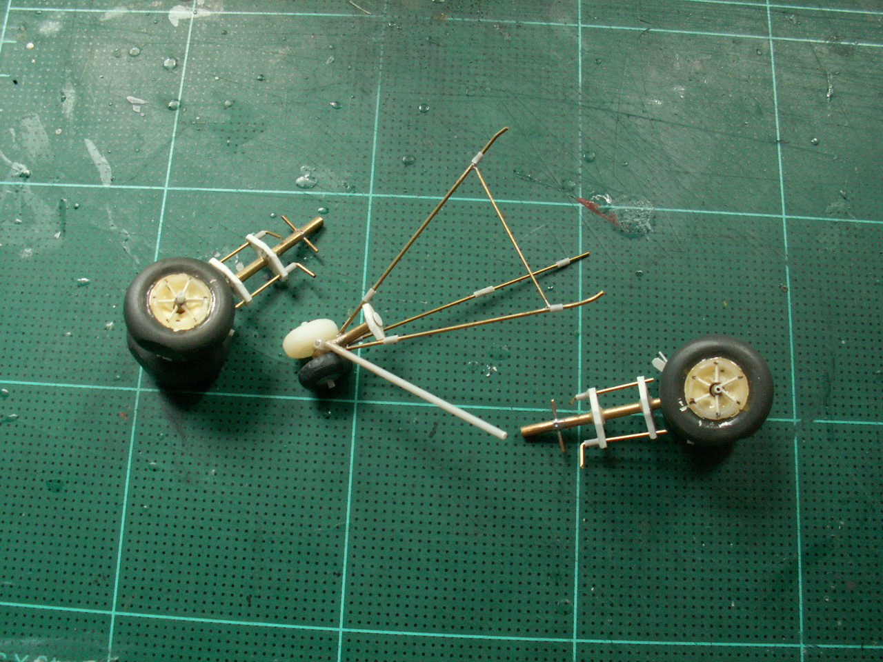
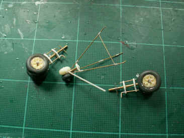
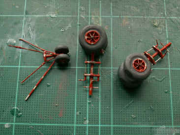
............This
was needed to be quite strong as it had to take the whole weight of the
model. Brass tubing and rod was the only answer. Out
came the trusty soldering iron, and away we went, see photo on right. I
also needed some wheels.
A rummage through the spares box produced just
the wheels required, the trouble was, the centres were wrong. Time for the
Dremel drill to come into
play. I ground the centres out and then had to rebuild them using
a great many short pieces of 15thou strip. Drilling
holes into the fuselage and trial fitting came next. The rear piece of
gear gave the most trouble and until it was fitted into the drilled holes,
it was quite fragile and required re-soldering a couple of times.
|
|
|
| g |
| Float
Retraction Arms - What a battle! |
| g |
 |
|
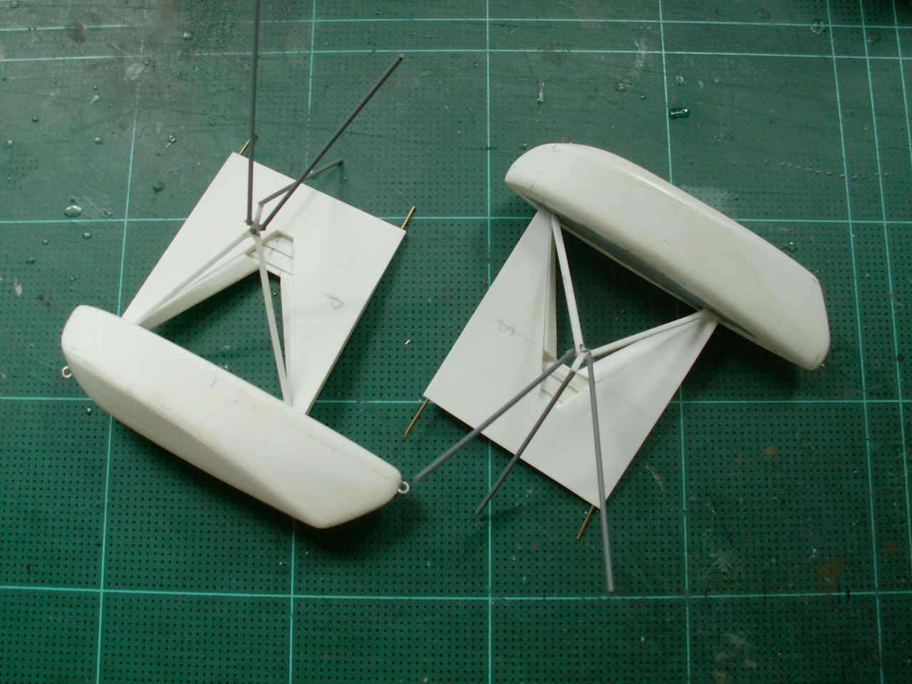
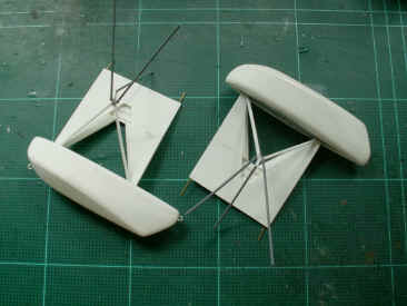
Left:
The float
retraction arms. To do these you have to be in the right mood. Everything
has to go like clockwork ---- mine didnt!
At least three hands are needed to accomplish this job there
was no-one else around, except our dogs, so I had to come up with a
solution.
Eventually,
after using books and some bits of balsa wood, the job was done, as you
can see.
|
|
| g |
| ............Back
to the Hull |
| g |
|
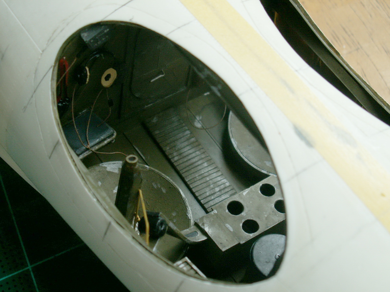
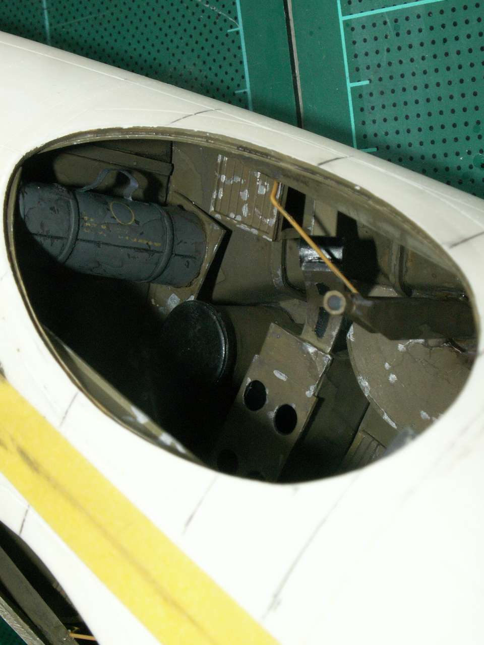
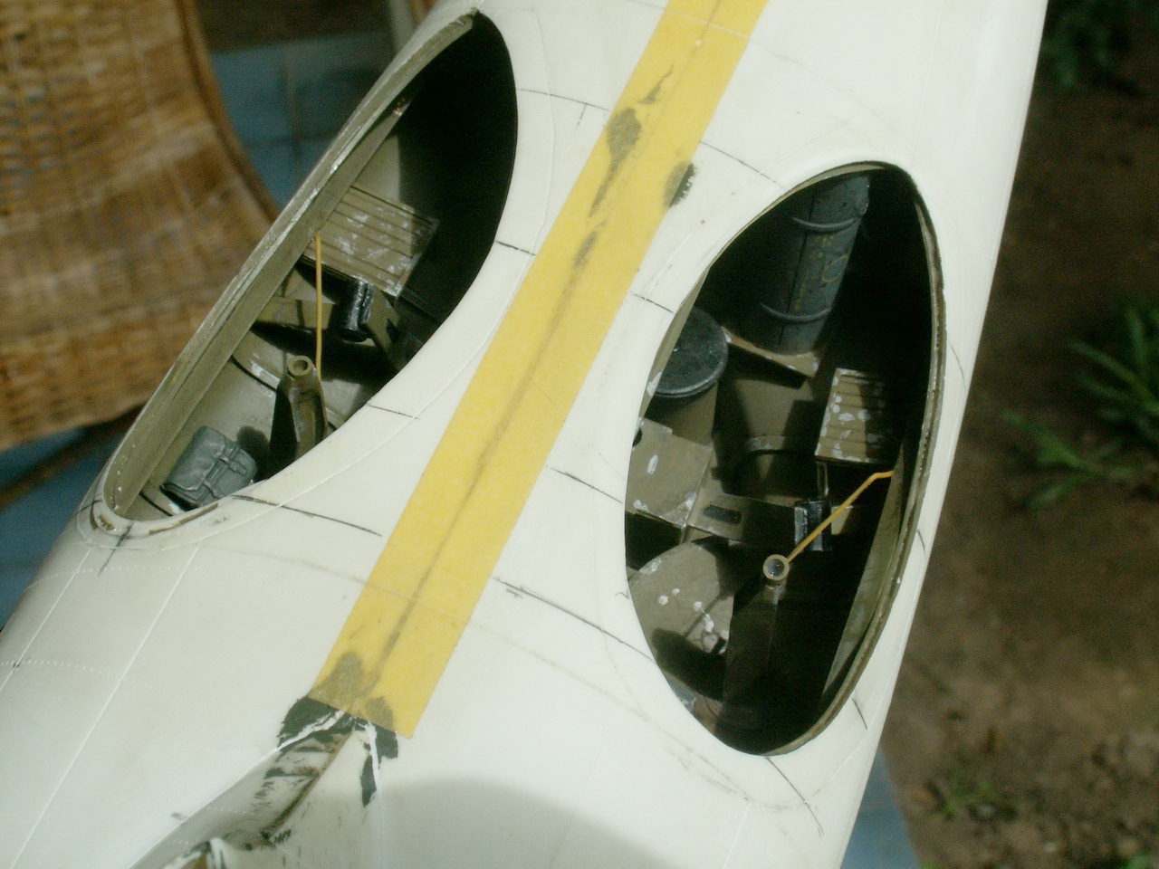
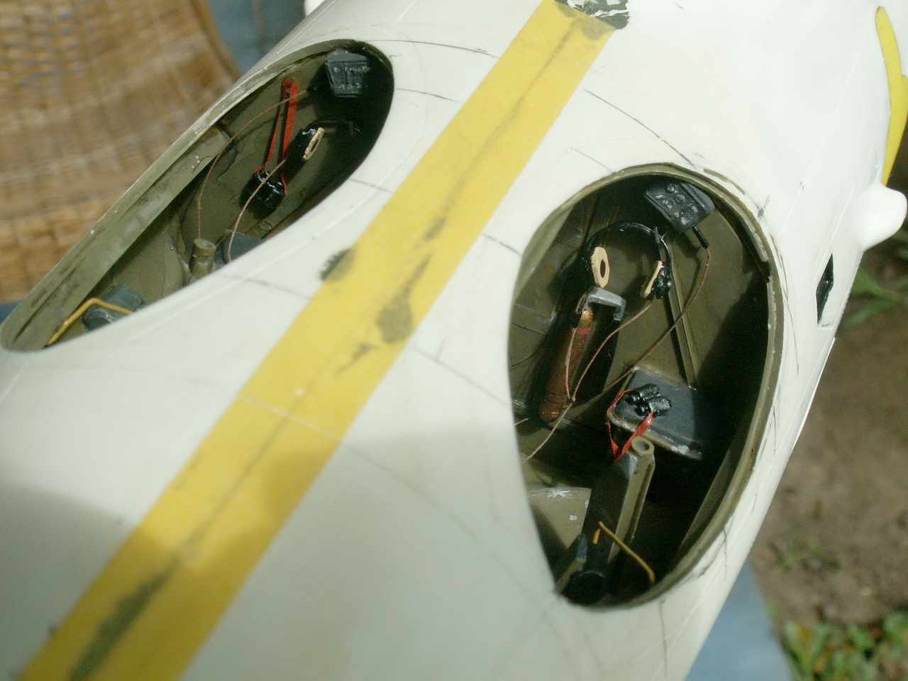
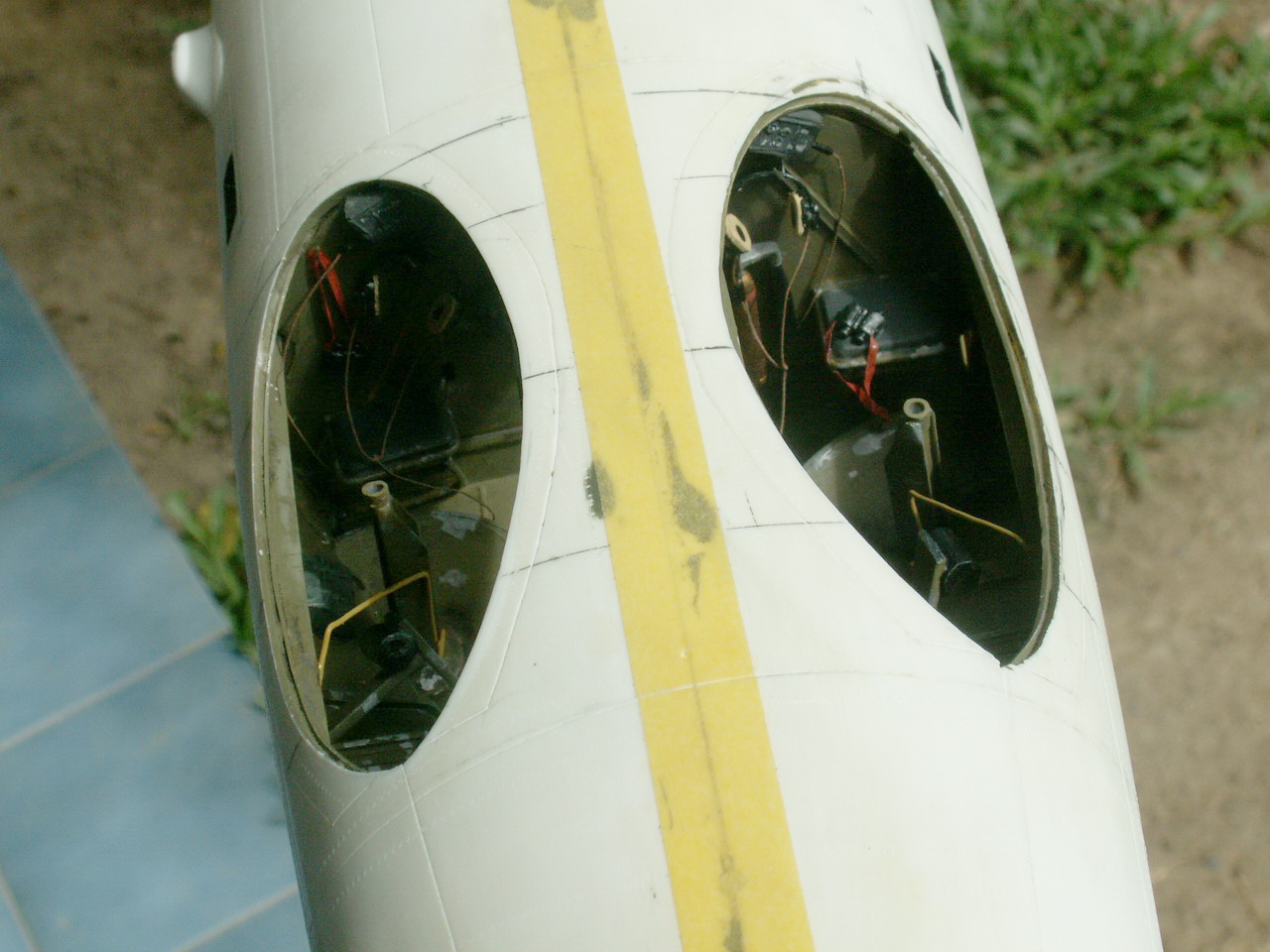
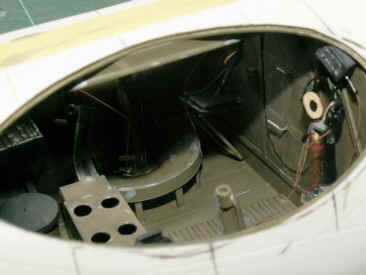
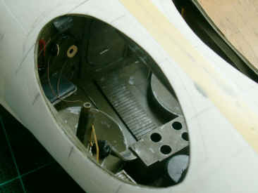
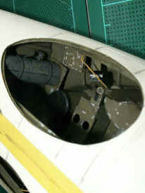
Back
for another go at the fuselage now. The
waist area, as seen in the series of photo's below, was kitted out with all manner of things, as you can see
from this series of photos. The large cut-outs in the fuselage here
provide a reasonable space to work.
|
| g |
  |
| g |
  |
| g |
  |
| g |
 g g |
| g |
|
A
word here about the waist canopies. The
canopies supplied in the kit are moulded in quite thick clear plastic and
the framing is too heavy. I
wanted one of my canopies open, with the sliding portion of the other one
slightly recessed. This required four canopies. The
solution make four new canopies.
The
canopies were fixed in an upside down position and resin poured in. This
process has to be done in layers, so as not to create too much heat as the
resin cures or it will melt the plastic canopy. Once
this was completed, the cured resin was extracted. These would form the
masters for vac-forming new canopies. I had to destroy the kit
canopies to get the new masters out, so was now totally committed.
The
framing on the masters was sanded off to leave two smooth shapes. Six
canopies were pulled from the masters (ALWAYS pull some extras, the
balls-up factor is high on canopies.) and trimmed ready for fitting
later.
|
| g |
 |
|
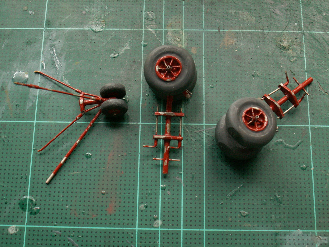
Left:
Painting
the beaching gear was next on my list. These items received a lot of wear,
so mine were given a coat of dull silver and, once that had dried, small
drops of Maskol applied here and there. A coat of red/brown was next and,
when dry, the pieces of Maskol picked/rubbed off.
I
always paint my tyres dark grey, NEVER black, Humbrol 67 Matt Tank Grey
seems about right to me.
|
|
| g |
| Waist
Mounted Armament Construction |
| g |
|
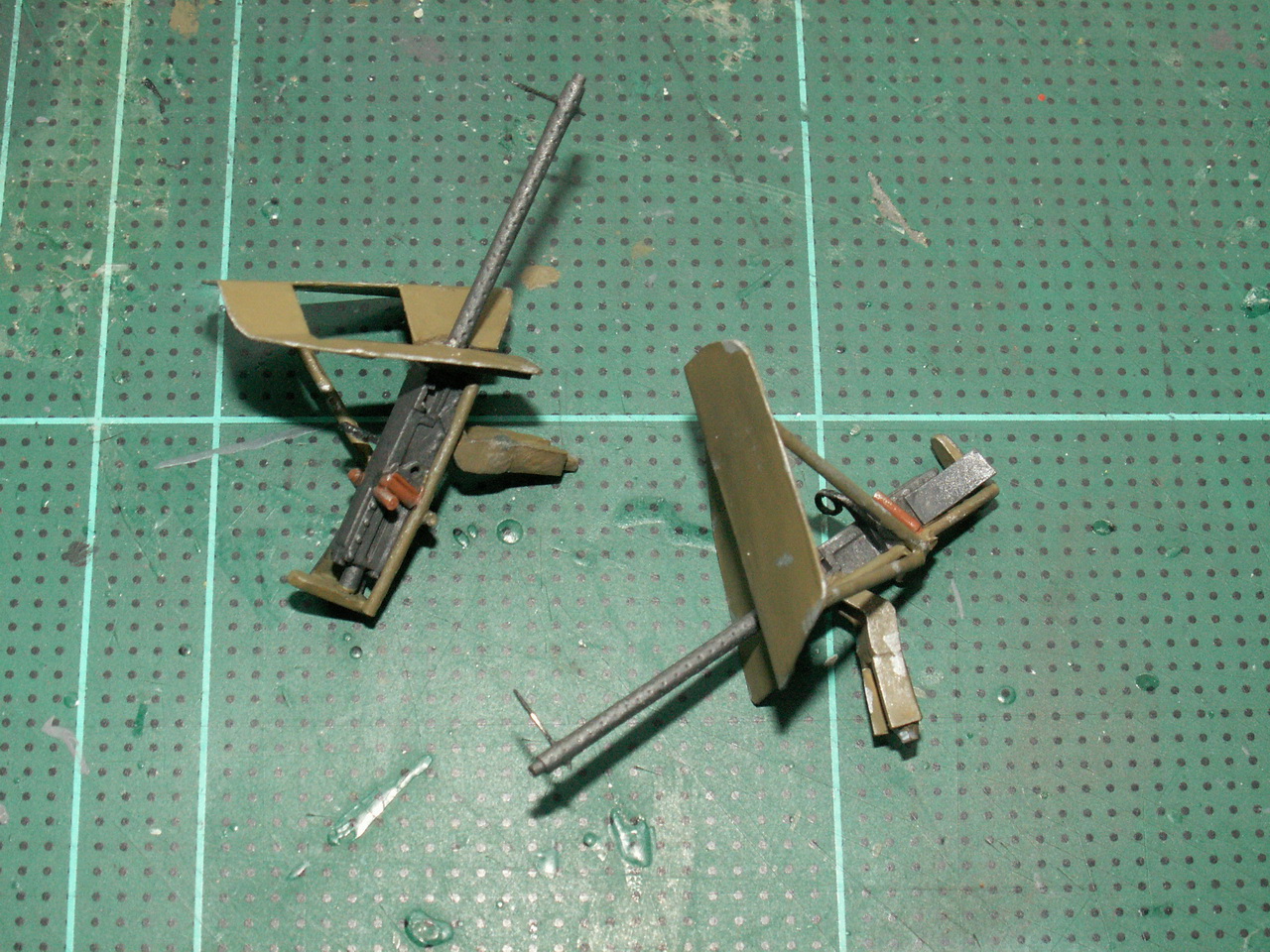
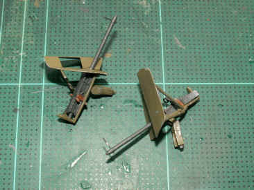
Right:
Luckily,
I found a couple of 0.5 and a pair of 0.303machine guns in my spares
box, which were ideal for this project.
The
waist 0.5s needed a shield and a few other bits and pieces, but were
soon ready for painting.
|
|
 |
| g |
| The
Cockpit, Nose Turret and Work Platforms |
| g |
|
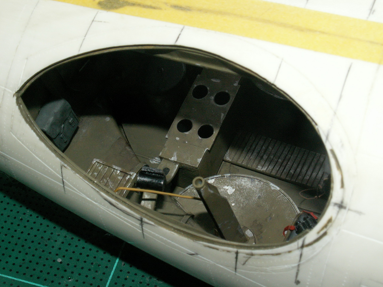
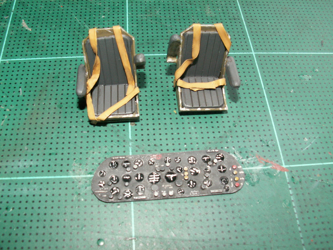
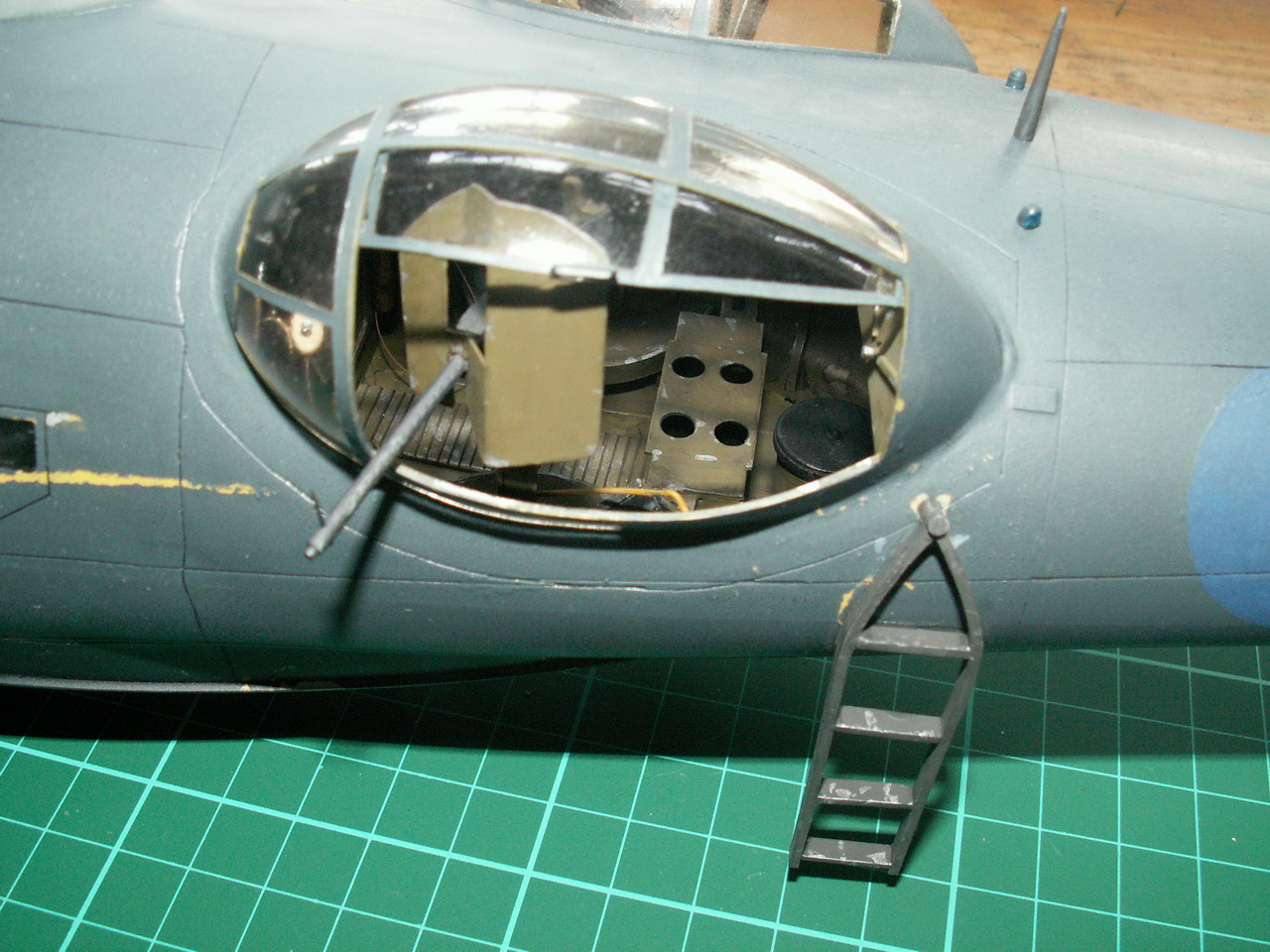
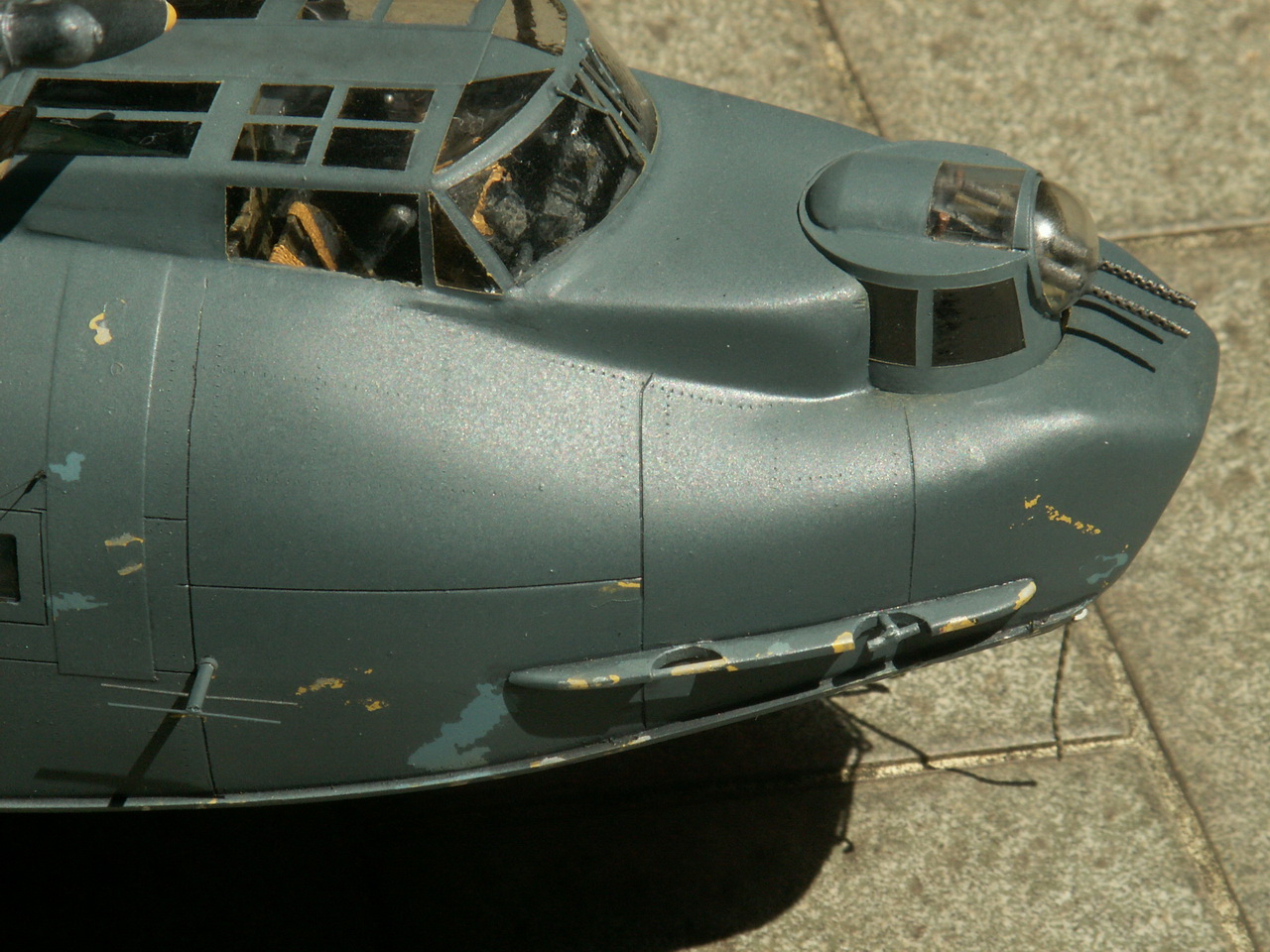
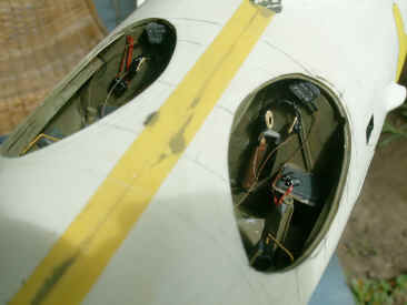
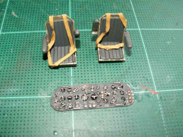
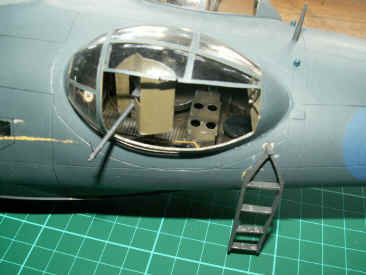
| Attention
was now turned to fitting out the pilots cockpit. Once
the canopy is on, the view inside here is very small, so not a great deal
of detailing is required. Shown here in the photo on the right are the seats and instrument panel. The
nose turret was modified into an eyeball turret using bits and
pieces of clear plastic I had in my spares box. The two 0.303s were
fitted and the turret installed into the nose. Sorry, no photo. |
|
 |
| g |
|
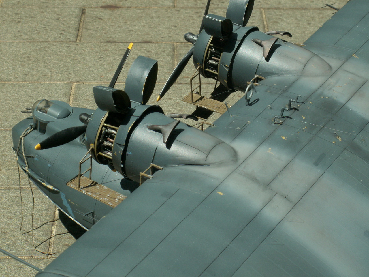
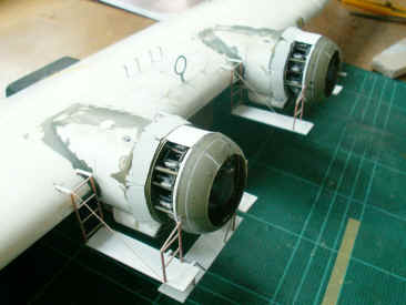
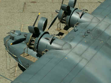
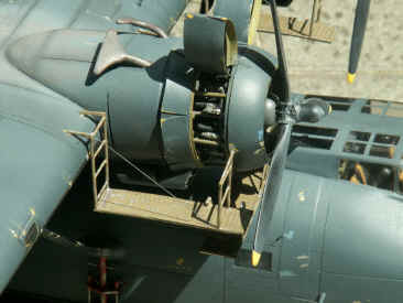
Below:
The working
platforms round the engines were next. These
were made from plastic sheet and rod. Plenty of photos of the real thing
is an essential here. |
| g |
  |
| g |
| Getting
Serious! |
| g |
|
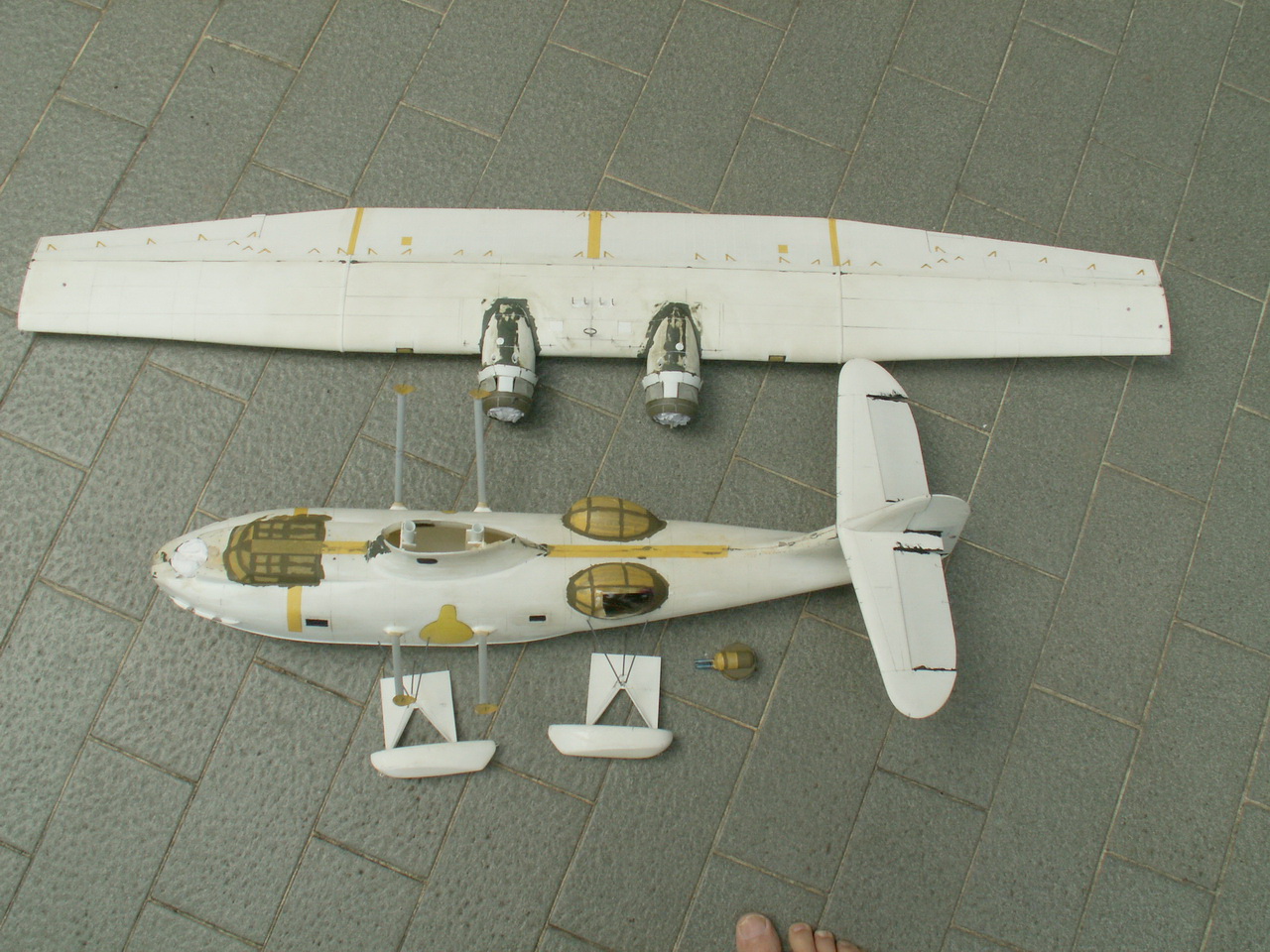
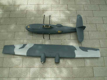
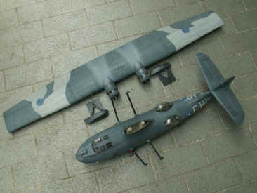
Now
we come to the serious bit.......
Right:
Here
the main components of the model are laid out prior to painting. Please
note - the toes shown in the bottom of the photo are not part of the model at all!
|
|
 |
| g |
| Final
Assembly, Painting and Decaling |
| g |
|
From
what Ive read, these Catalina's arrived in Australia as amphibians and
were converted back to flying boats. They were coloured in the, then,
standard USN colours of sea blue/intermediate blue with white undersides.
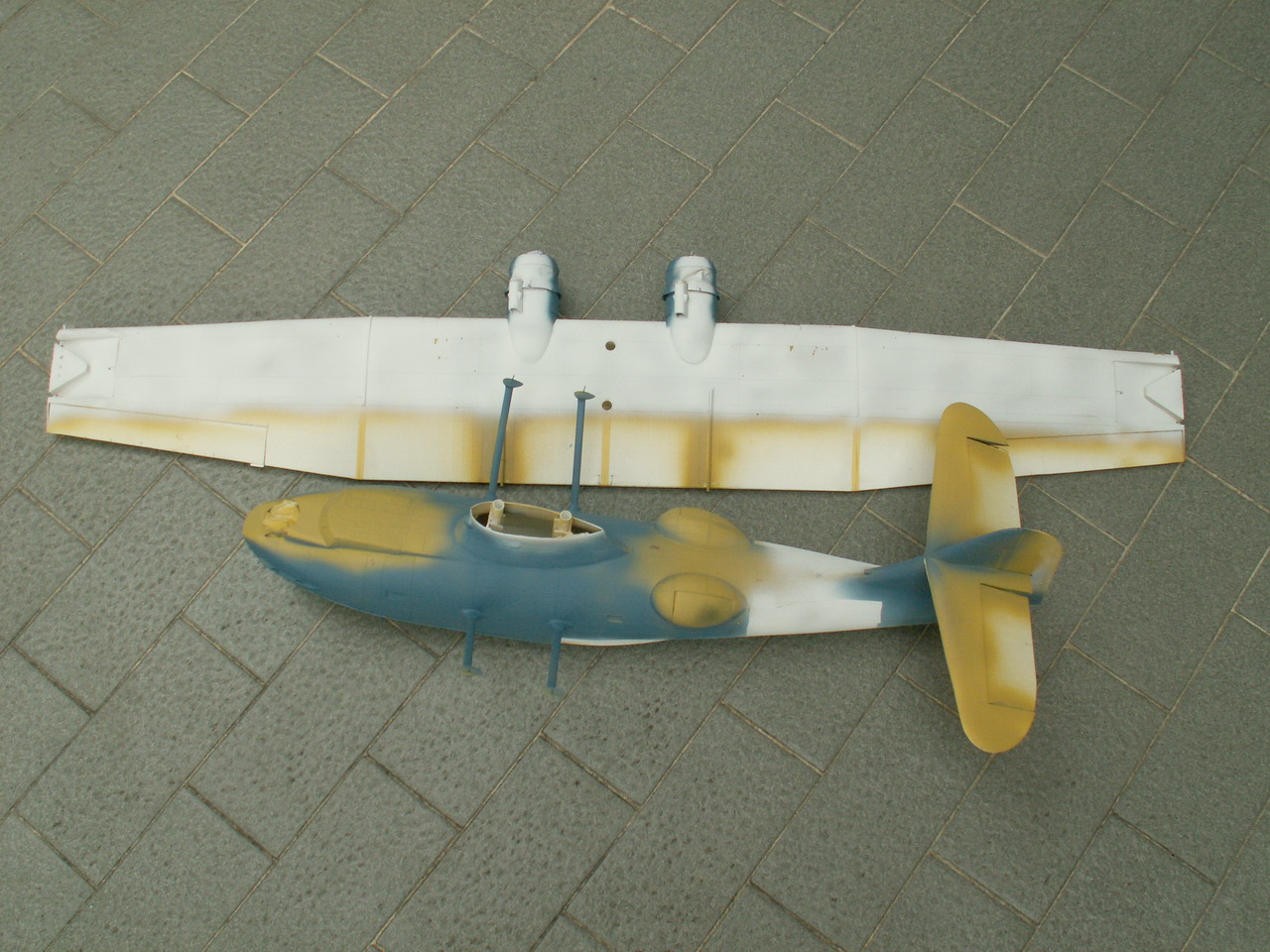
I
have assumed that they were primed in yellow zinc chromate. In Australia,
these machines were re-painted in dark ocean blue uppers(FS35044), with an
extra dark sea grey camouflage pattern on the wings and matt black
underneath. The EDSG faded very rapidly, and soon became a light grey.
So,
out
with the airbrush!.
I
started off by spraying all the metal areas yellow zinc chromate Humbrol
81 Matt Pale Yellow.
Again,
dabs of Maskol were applied to various spots. Matt white Humbrol 34, was
applied to the underside of the wing and tailplane. More spots of Maskol
came next, followed by some intermediate blue Humbrol 144, going onto the
fuselage sides and fin. Yet more dabs of Maskol followed.
Very
pale blue/grey went on the fuselage sides, aft of the waist canopies and
the squadron codes applied in masking tape. The edges of the masking tape
were then given a brush coat of Klear/Future and left to dry. This coat of
Klear prevents the next coat of paint from bleeding under the
masking tape a trick worth remembering.
A
squirt of Humbrol 25 Matt Blue then went onto the fuselage side, where the
roundel would appear, another squirt onto the fin, where the fin flash
goes and finally, another squirt onto the top of the wing, where those
roundels appear. When dry, pieces of masking tape covered these areas,
followed by the Klear treatment.
I
had very little Humbrol 33 Matt Black, so had to revert to Gunze Mr. Color
92 Semi-Gloss Black (good stuff). This paint dries very rapidly, so I was
soon masking, ready for the next colour.
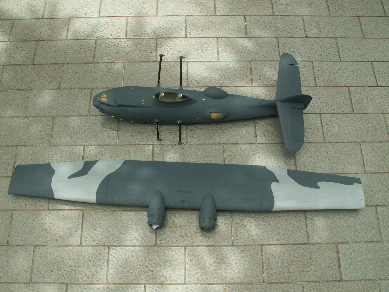
Dark
Ocean Blue was the next one to go on and I found that Humbrol 96 Matt RAF
Blue, with some black added, gave a good rendition of the faded colour
that I wanted.
Now,
faded EDSG could be a problem, I plumbed for Humbrol 165 Satin Medium Sea
Grey. Some thin sausages of Blue Tac were laid across the wing and then
the rest was masked. A quick squirt of MSG and all the large pieces of
the model were done.
|
| g |
  |
| g |
 |
| g |
|
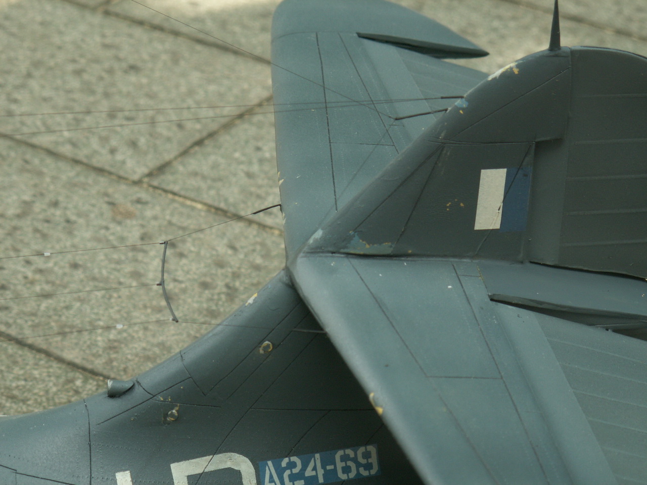
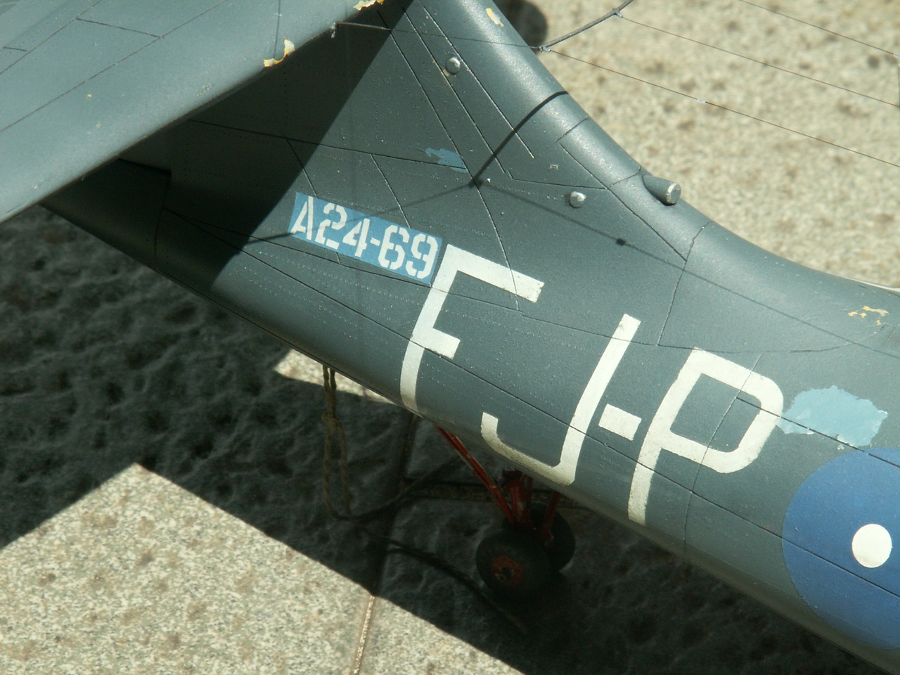
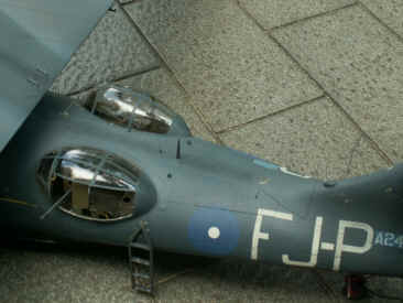
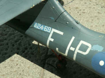
The
whole airframe was then given a coat of matt varnish, to even out all the
different paints used. WAIT!!
Just before I did that, I applied the serial numbers, which were on a
backing colour of intermediate blue, onto the rear fuselage.
Next
came the highlighting of the fabric areas and the exhaust staining. After
that the great unmasking ceremony could begin!
|
| g |
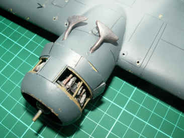 |
| Left:
Shown
here are the spade shaped exhausts, these were made from plastic tubing,
plastic sheet, solder and epoxy putty. Note the chipped paint. |
|
| g |
| Right:
A close-up view of the finished port waist area. |
|
 |
| g |
| At
Last! The Finished Model....... |
|
g |
|
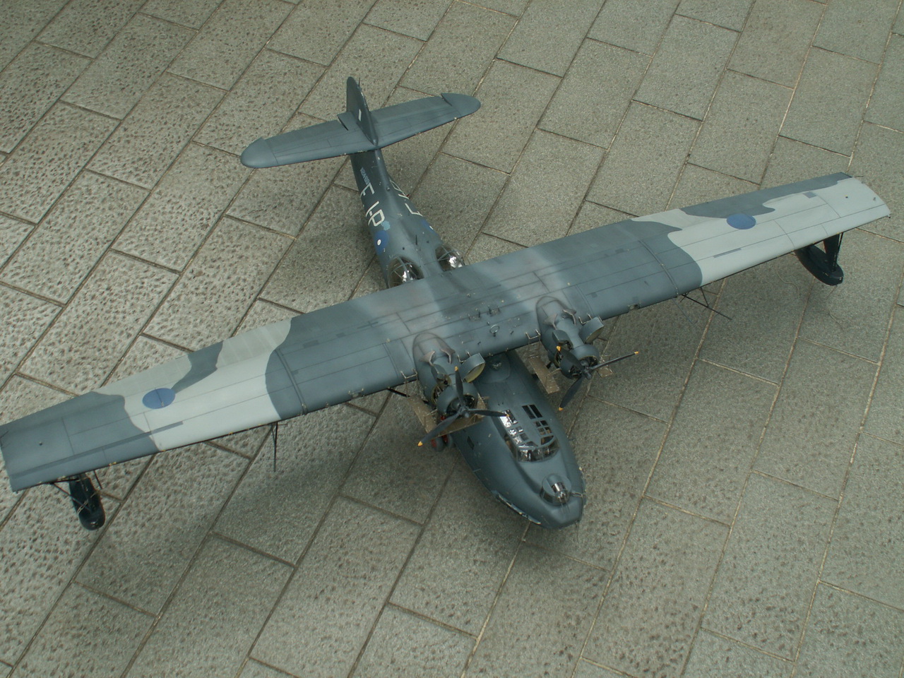
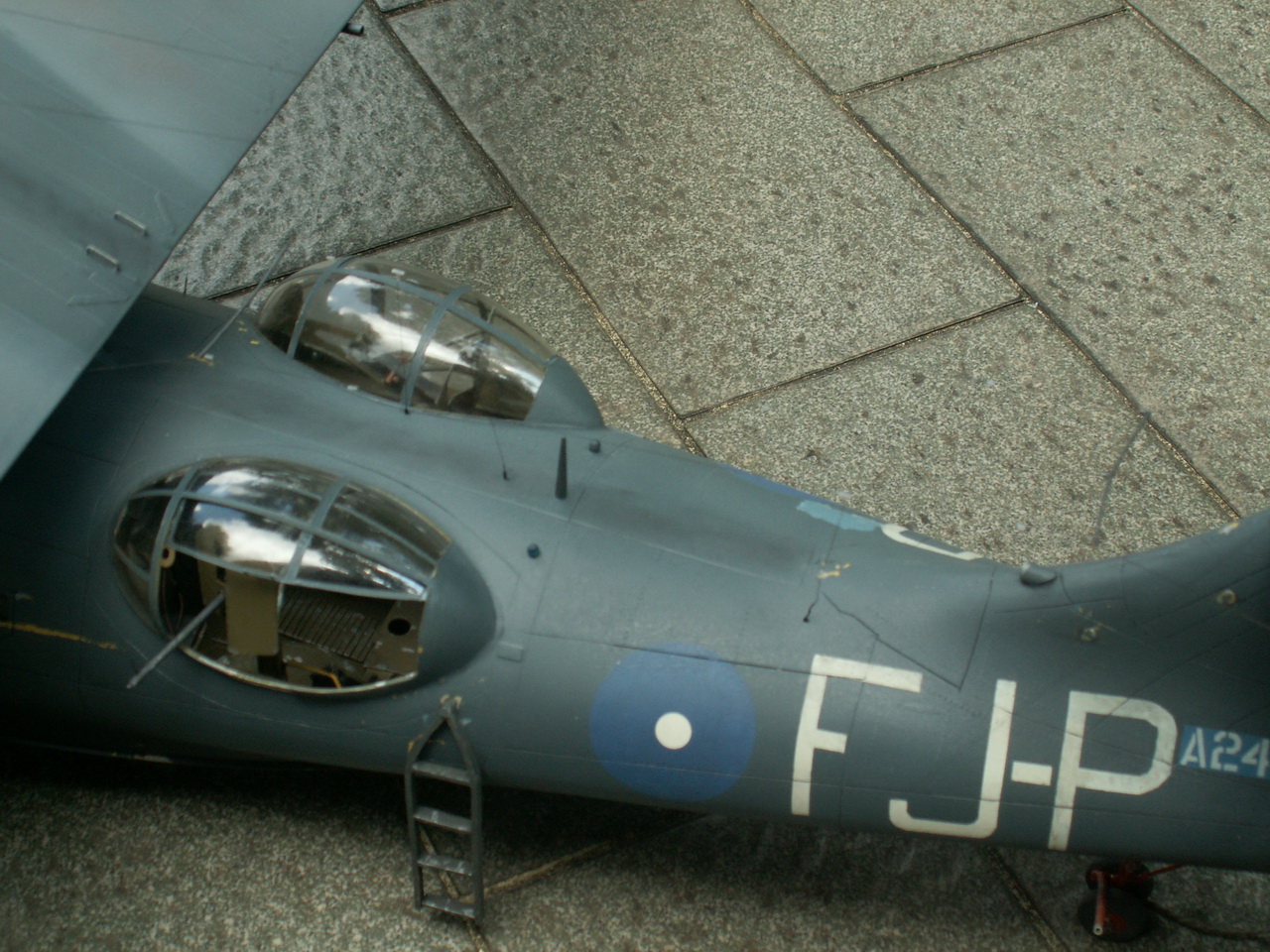
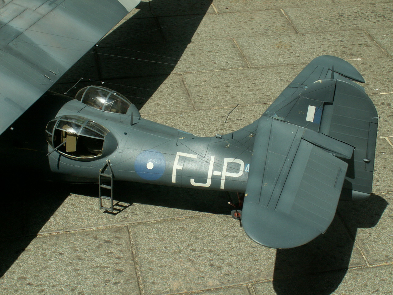
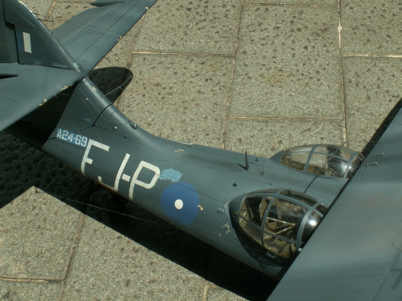
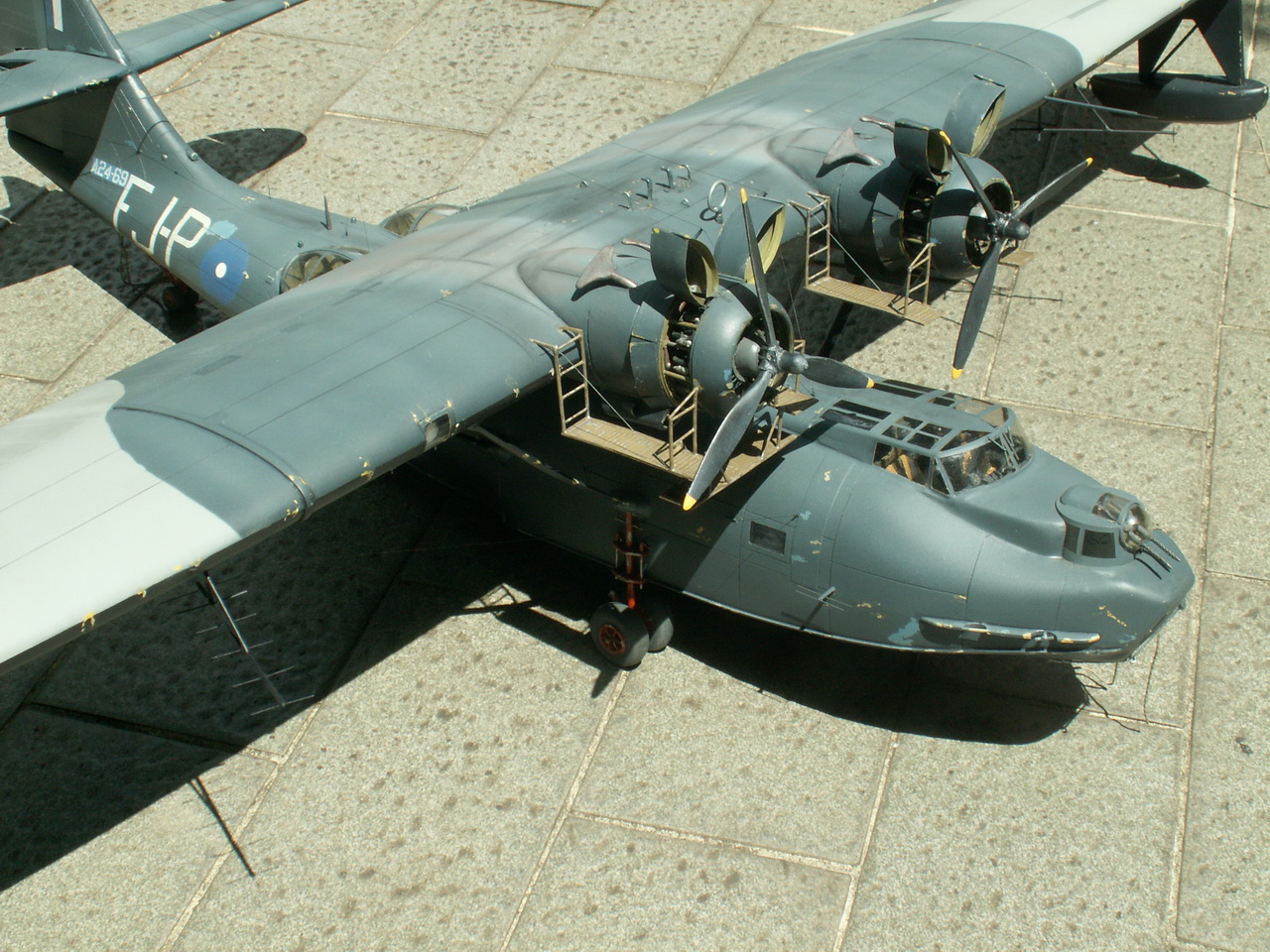
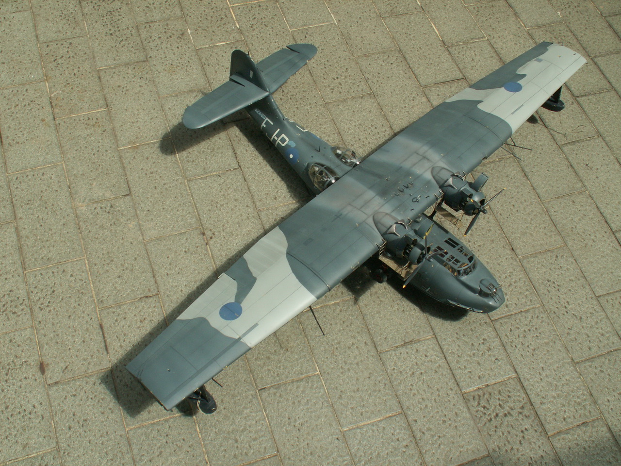
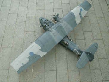
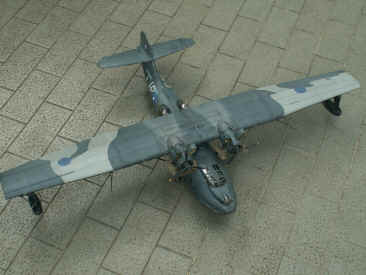
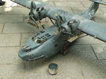
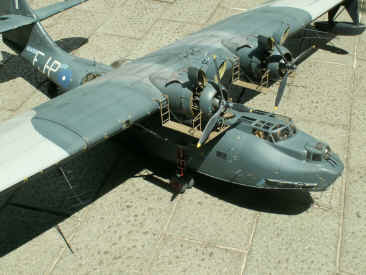
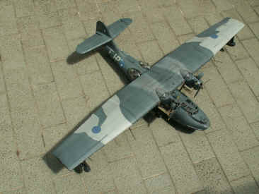
Heres
some views of the finished model.........
Its
a pity the photos dont show up the great many wire and rod aerials
carried by this aircraft. All the wire aerials are human hair (I have a
friend here with very long black hair I borrowed a few strands!)
Handling
this model is a nightmare, Im so afraid of breaking one of the aerials.
|
| g |
  |
| g |
  |
| g |
  |
| g |
  |
| g |
  |
|
  |
|
  |
| g |
|
Making
a vac-form model for the first time may appear daunting to some - well, the
only way to get any experience with building them is to have a go. Dont
go for a small 1/72 model for a start or youll soon get bored rubbing
down small tailplane and fin pieces. Go for something a bit larger, like a
1/32 Saab Tunan or Mig 15/17 and please be careful if you use cyano as an
adhesive for the larger parts, as I do. |
| g |
|
Glenn
Ping |
|